Rockwell Automation Publication 1766-UM001I-EN-P - June 2015 189
Troubleshooting Your System Appendix C
Calling Rockwell
Automation for Assistance
If you need to contact Rockwell Automation or local distributor for assistance, it
is helpful to obtain the following (prior to calling):
• controller type, series letter, revision letter, and firmware (FRN) number of
the controller
• controller indicator status
Hardware-Specific
Error
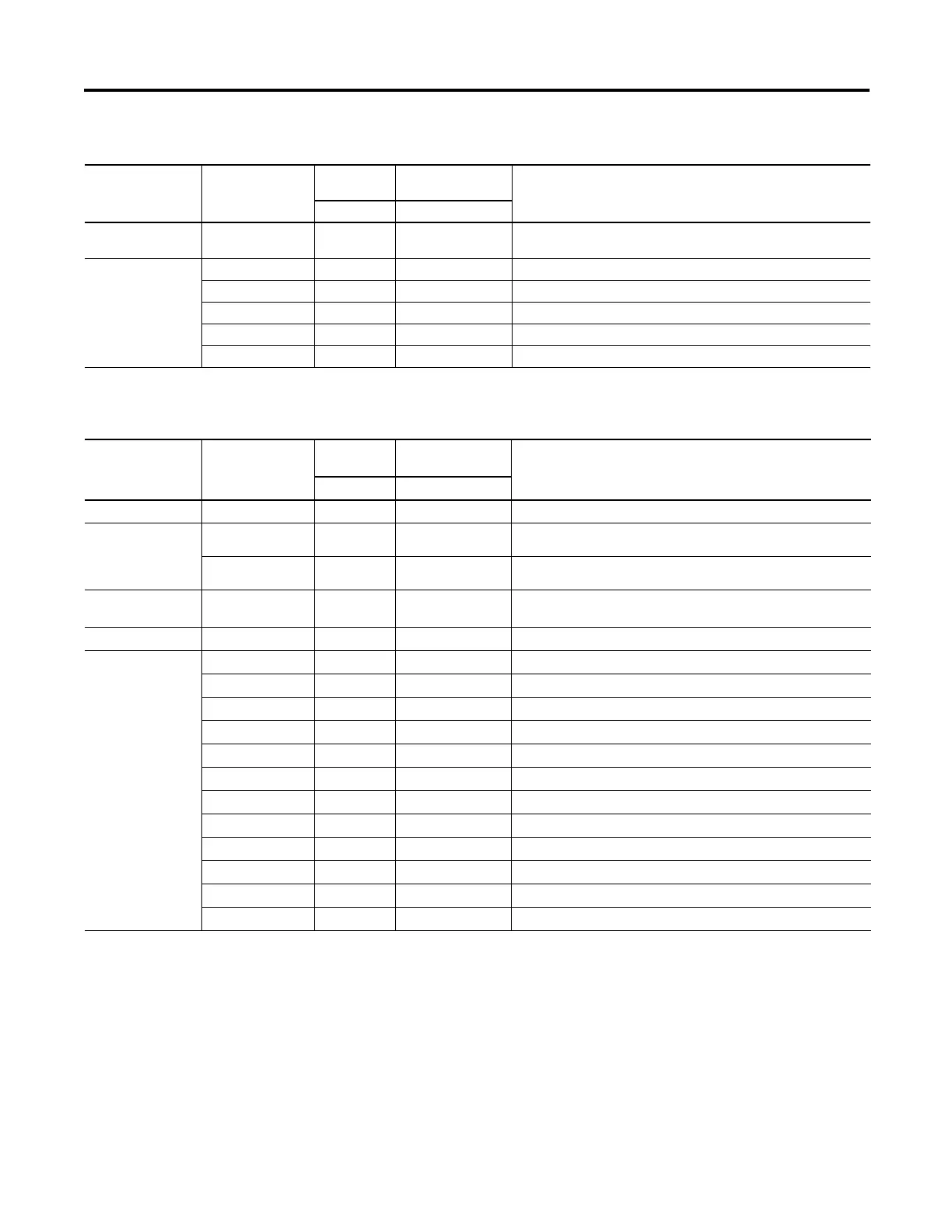
X210 001 0 0001 0000 Reserved
Configuration Error X400 010 0 0000 0000 General configuration error; no additional information
X401 010 0 0000 0001 Invalid input data format selected (channel 0)
X402 010 0 0000 0010 Invalid input data format selected (channel 1)
X403 010 0 0000 0011 Invalid output data format selected (channel 0)
X404 010 0 0000 0100 Invalid output data format selected (channel 1)
(1)
X represents “Don’t Care”.
Extended Error Codes for 1762-IF2OF2
Error Type Hex Equivalent
(1)
Module Error
Code
Extended Error
Information Code
Error Description
Binary Binary
Extended Error Codes for 1762-IF4 and 1762-OF4
Error Type Hex Equivalent
(1)
Module
Error Code
Extended Error
Information Code
Error Description
Binary Binary
No Error X000 000 0 0000 0000 No error
General Common
Hardware Error
X200 001 0 0000 0000 General hardware error; no additional information
X201 001 0 0000 0001 Power-up reset state
Hardware-
Specific Error
X300 001 1 0000 0000 Reserved
Configuration Error X400 010 0 0000 0000 General configuration error; no additional information
X401 010 0 0000 0001 Invalid range select (Channel 0)
X402 010 0 0000 0010 Invalid range select (Channel 1)
X403 010 0 0000 0011 Invalid range select (Channel 2)
X404 010 0 0000 0100 Invalid range select (Channel 3)
X405 010 0 0000 0101 Invalid filter select (Channel 0) – 1762-IF4 only
X406 010 0 0000 0110 Invalid filter select (Channel 1) – 1762-IF4 only
X407 010 0 0000 0111 Invalid filter select (Channel 2) – 1762-IF4 only
X408 010 0 0000 1000 Invalid filter select (Channel 3) – 1762-IF4 only
X409 010 0 0000 1001 Invalid format select (Channel 0)
X40A 010 0 0000 1010 Invalid format select (Channel 1)
X40B 010 0 0000 1011 Invalid format select (Channel 2)
X40C 010 0 0000 1400 Invalid format select (Channel 3)
(1)
X represents “Don’t Care”.

 Loading...


