Rockwell Automation Publication 1766-UM001I-EN-P - June 2015 33
Wire Your Controller Chapter 3
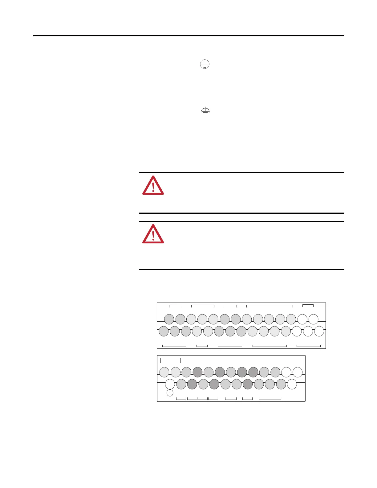
Terminal Block Layouts
Figure 3 - 1766-L32BWA/L32BWAA
This symbol denotes a protective earth ground terminal which
provides a low impedance path between electrical circuits and earth
for safety purposes and provides noise immunity improvement. This
connection must be made for safety purposes on AC-powered
controllers.
This symbol denotes a functional earth ground terminal which
provides a low impedance path between electrical circuits and earth
for non-safety purposes, such as noise immunity improvement.
ATTENTION: When you connect or disconnect the Removable
Terminal Block (RTB) with field side power applied, an electrical arc
can occur. This could cause an explosion in hazardous location
installations. Be sure that power is removed or the area is
nonhazardous before proceeding.
When used in a Class I, Division 2, hazardous location, this equipment
must be mounted in a suitable enclosure. All wiring must be in
accordance with Class I, Division 2 wiring methods of Article 501 of
the National Electrical Code and/or in accordance with Section 18-1J2
of the Canadian Electrical Code, and in accordance with the authority
having jurisdiction.
IN1
IN0 IN2
IN3
COM 0
IV0(+) IV2(+)
COM 1
IV1(+) IV3(+)
IN5 IN7
IN4 IN6
COM 2
IN8 IN10
IN9 IN11
COM 3
IN13 IN15 IN17 IN19
IN12 IN14 IN16 IN18
COM
ANA
L1
DC0
OV1
OUT0
OUT1 OUT2 OUT3 OUT4
OUT5
OUT7 OUT8 OUT10
OUT6 OUT9 OUT11
OV0
VAC
L2/N
VAC
VAC
DC1
VAC
DC2
VAC
DC3
VAC
DC4
VAC
DC6
VAC
COM
ANA
DC5
VAC
Group 0 Group 1 Group 2 Group 3 Group 5Group 4 Group 6
Input Terminal Block
Output Terminal Block
44524

 Loading...


