EasyManuals Logo

Allen-Bradley MicroLogix 1400 User Manual

Allen-Bradley MicroLogix 1400
404 pages
To Next Page IconTo Next Page
To Previous Page IconTo Previous Page
Page #33 background imageLoading...
Page #33 background image
Rockwell Automation Publication 1766-UM001I-EN-P - June 2015 19
Install Your Controller Chapter 2
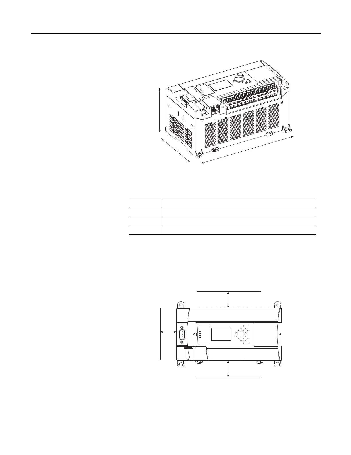
Controller Mounting
Dimensions
Controller and Expansion
I/O Spacing
The controller mounts horizontally, with the expansion I/O extending to the
right of the controller. Allow 50 mm (2 in.) of space on all sides of the controller
system for adequate ventilation. Maintain spacing from enclosure walls, wireways,
adjacent equipment, and so on, as shown below.
Dimension Measurement
A 90 mm (3.5 in.)
B 180 mm (7.087 in.)
C 87 mm (3.43 in.)
C
B
A
1766-L32BWA, 1766-L32AWA, 1766-L32BXB, 1766-L32BWAA,
1766-L32AWAA, 1766-L32BXBA
44516
ESC
OK
Top
Bottom
Side
44517

Table of Contents

Other manuals for Allen-Bradley MicroLogix 1400

Questions and Answers:

Question and Answer IconNeed help?

Do you have a question about the Allen-Bradley MicroLogix 1400 and is the answer not in the manual?

Allen-Bradley MicroLogix 1400 Specifications

General IconGeneral
Processor32-bit
Expansion ModulesUp to 7 expansion I/O modules
Power Supply24V DC or 120/240V AC
Programming SoftwareRSLogix 500
Communication PortsEthernet, RS-232/RS-485 combo port
Controller TypeProgrammable Logic Controller (PLC)
SeriesMicroLogix
Digital Outputs12
Analog Inputs6 (embedded)
Analog Outputs2 (embedded)
High-Speed Counter6 high-speed counters
Pulse Output2 (embedded)
Ethernet PortYes

Related product manuals