42 Rockwell Automation Publication 1766-UM001I-EN-P - June 2015
Chapter 3 Wire Your Controller
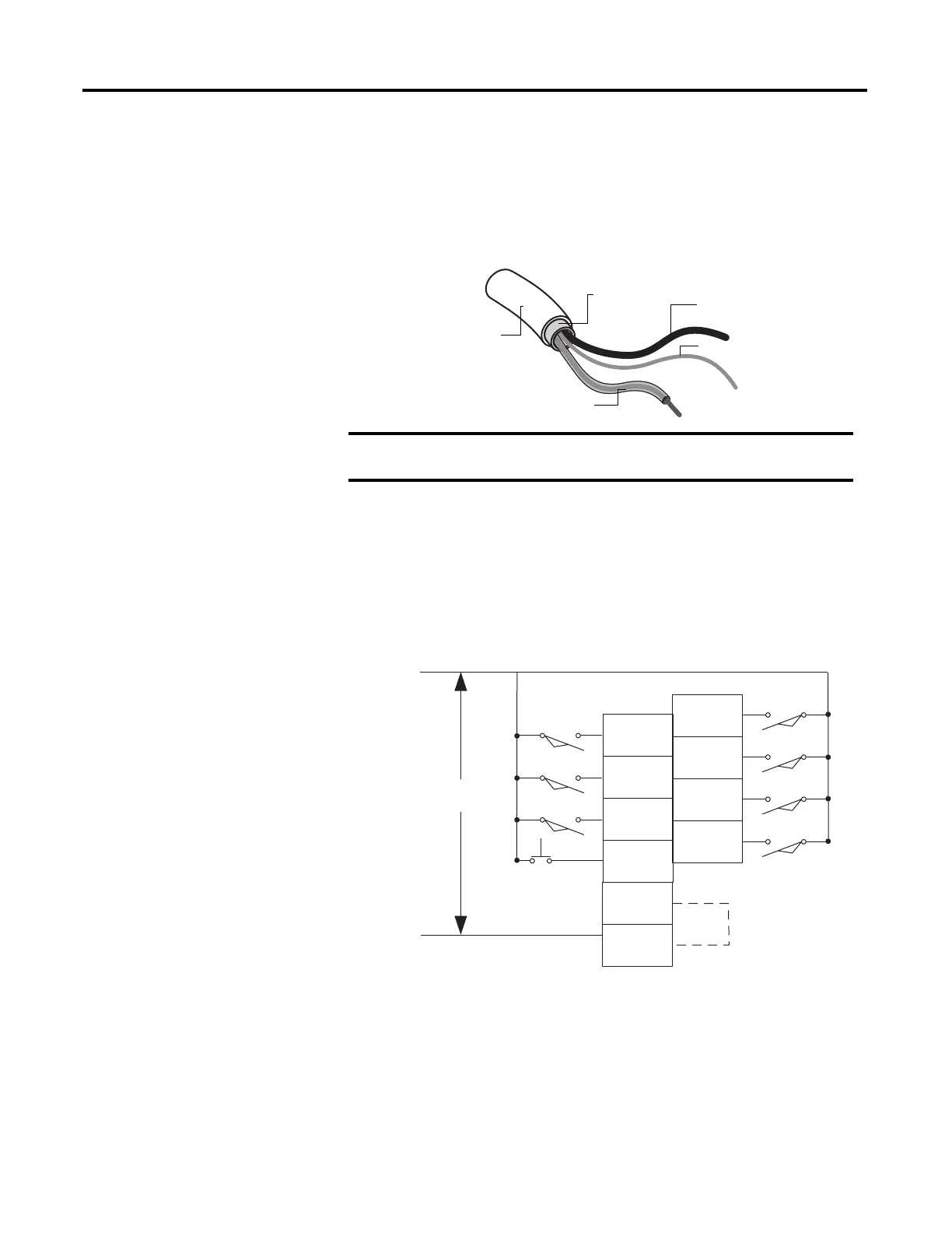
Grounding Your Analog Cable
Use shielded communication cable (Belden #8761). The Belden cable has two
signal wires (black and clear), one drain wire, and a foil shield. The drain wire and
foil shield must be grounded at one end of the cable.
Expansion I/O Wiring
Digital Wiring Diagrams
The following illustrations show the digital expansion I/O wiring diagrams.
Figure 15 - 1762-IA8 Wiring Diagram
Do not ground the drain wire and foil shield at both ends of the
cable
Foil Shield
Black Wire
Drain Wire
Clear Wire
Insulation
44531
IN 7
IN 5
IN 3
IN 1
AC
COM
IN 6
IN 4
IN 2
IN 0
L1
L2
100/120V AC
AC
COM
Common
connected
internally.
44570

 Loading...


