Rockwell Automation Publication 1766-UM001I-EN-P - June 2015 93
Using the LCD Chapter 5
Setting Values
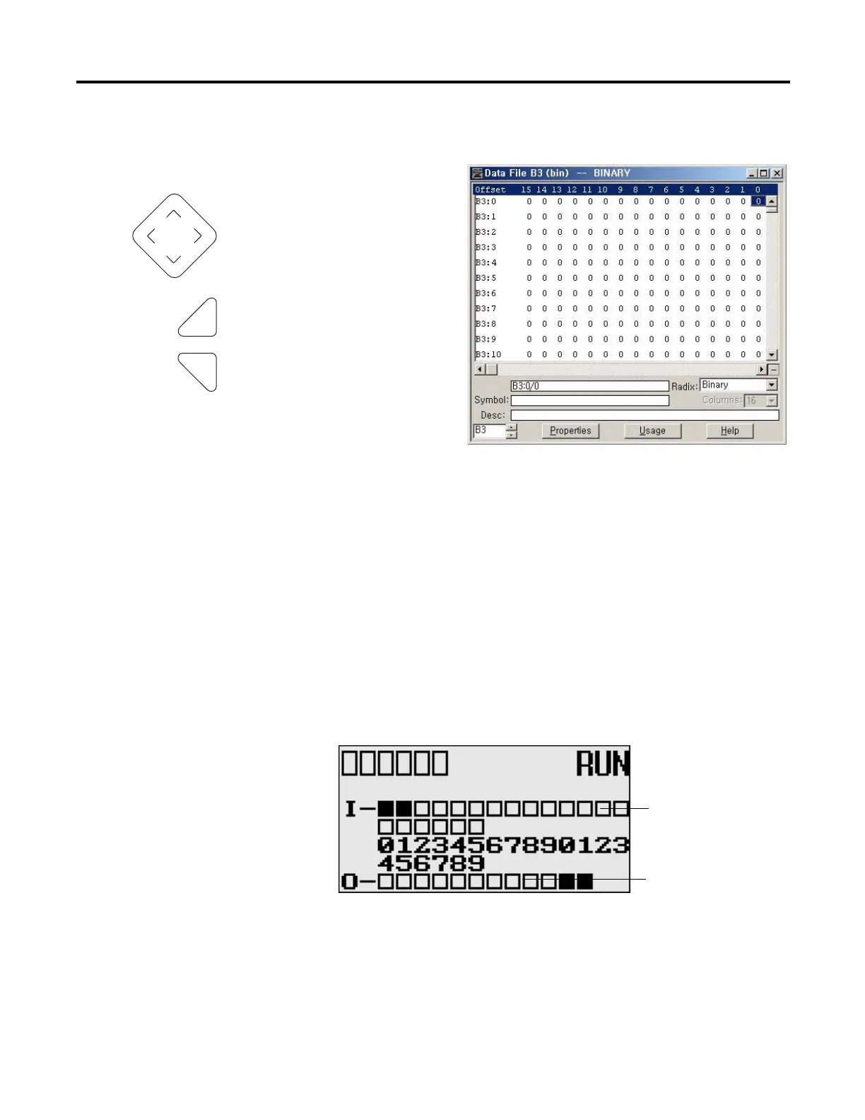
I/O Status
The MicroLogix 1400 provides I/O status indicators on the LCD screen. You
can view the status of inputs and outputs on the I/O Status screen on the LCD, as
shown below. The I/O status indicators on this screen are updated every 100 ms
to reflect the current I/O status in real time, regardless of controller scan time.
A solid rectangle is displayed when the input or output is energized. An empty
rectangle is displayed when the input or output is not energized.
Change value = up/down arrows
Move cursor between digits = left/right arrows
Stores Entries
Retain previous value
Left/right arrow moves the cursor between the digits of the
value .
Up/down arrow changes the value.
Up arrow = increment
Down arrow = decrement
Output status indicators (12)
Input status indicators (20)
COM
M
0
COMM
1
DCOMM
B
A
T
.
L
O
U
-
DI
SP
COM
M
2

 Loading...


