Rockwell Automation Publication 1766-UM001I-EN-P - June 2015 73
Communication Connections Chapter 4
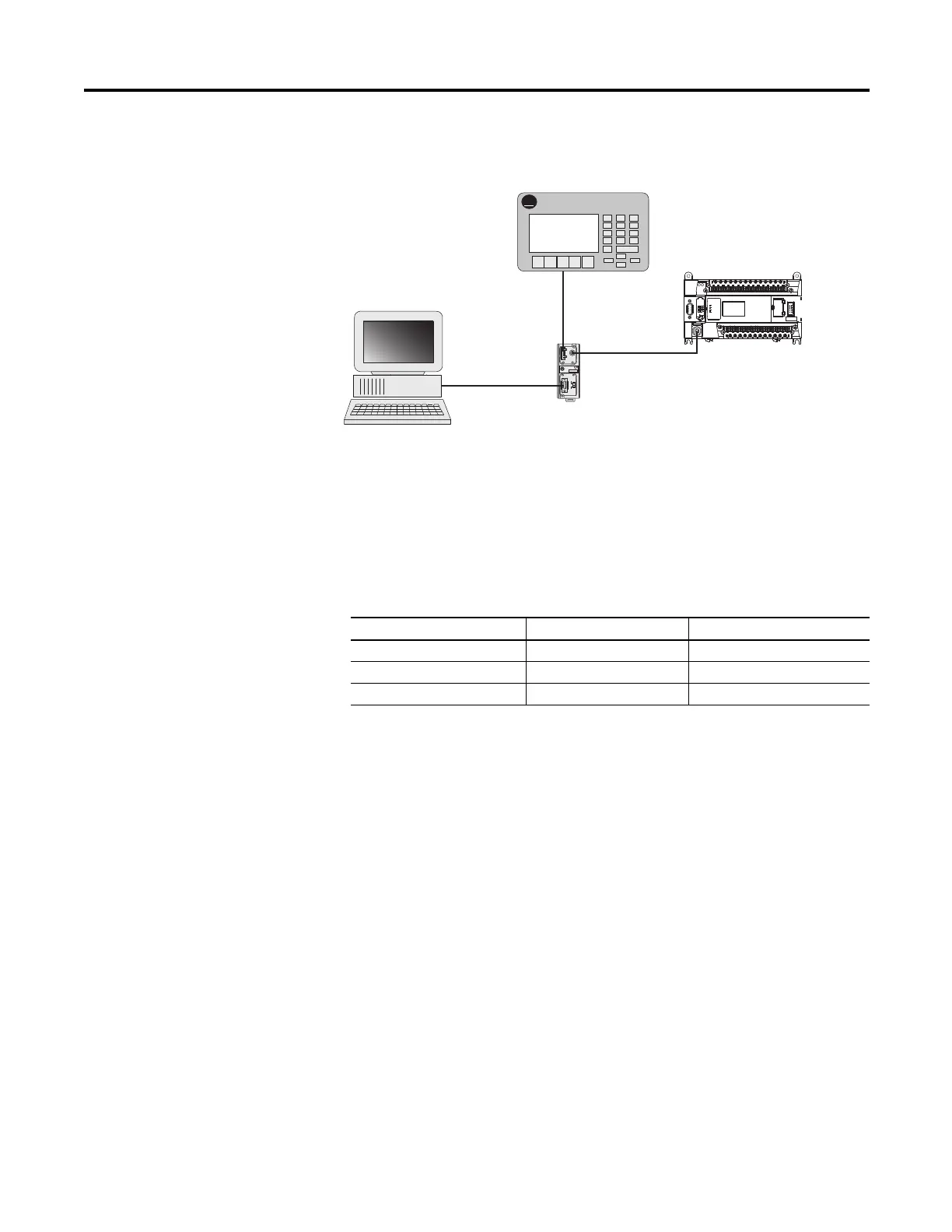
Typical 3-Node Network (Channel 0 Connection)
Recommended Tools
To connect a DH-485 network to additional devices, you need tools to strip the
shielded cable and to attach the cable to the AIC+ Advanced Interface
Converter. We recommend the following equipment (or equivalent):
DH-485 Communication Cable
The suggested DH-485 communication cable is either Belden #3106A or #9842.
The cable is jacketed and shielded with one or two twisted-wire pairs and a drain
wire.
One pair provides a balanced signal line and one additional wire is used for a
common reference line between all nodes on the network. The shield reduces the
effect of electrostatic noise from the industrial environment on network
communication.
The communication cable consists of a number of cable segments daisy-chained
together. The total length of the cable segments cannot exceed 1219 m (4000 ft).
However, two segments can be used to extend the DH-485 network to 2438 m
(8000 ft). For additional information on connections using the AIC+, refer to
the Advanced Interface Converter (AIC+) User Manual, publication 1761-6.4.
TERM
A
B
COM
SHLD
CHS GND
TX
TX PWR
TX
DC SOURCE
CABLE
EXTERNAL
A-B
PanelView
PanelView 550
MicroLogix 1400
1761-CBL-AM00
or 1761-CBL-HM02
1747-CP3 or
1761-CBL-AC00
RJ45 port
1761-CBL-AS09
or 1761-CBL-AS03
CH0
44599
Working with Cable for DH-485 Network
Description Part Number Manufacturer
Shielded Twisted Pair Cable #3106A or #9842 Belden
Stripping Tool Not Applicable Not Applicable
1/8” Slotted Screwdriver Not Applicable Not Applicable

 Loading...


