EasyManuals Logo

Allen-Bradley MicroLogix 1400 User Manual

Allen-Bradley MicroLogix 1400
404 pages
To Next Page IconTo Next Page
To Previous Page IconTo Previous Page
Page #97 background imageLoading...
Page #97 background image
Rockwell Automation Publication 1766-UM001I-EN-P - June 2015 83
Communication Connections Chapter 4
– rated NEC Class 2
Make a hard-wired connection from the external supply to the screw
terminals on the bottom of the AIC+.
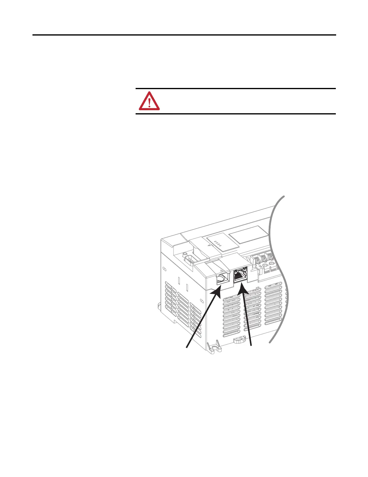
Connecting to Ethernet
You can connect directly a MicroLogix 1400 to an Ethernet network via the
Ethernet port (Channel 1). You do not need to use an Ethernet interface card,
such as the Ethernet Interface (ENI) and (ENIW), catalog number
1761-NET-ENI and 1761-NET-ENIW, to connect your MicroLogix 1400
controller to an Ethernet network. For additional information on connecting to
an Ethernet network, see Connecting to Networks via Ethernet Interface on
page 351.
ATTENTION: If you use an external power supply, it must be 24V
DC (-15%/+20%). Permanent damage results if miswired with the
wrong power source.
RS-232/485 Port (Channel 0)
Ethernet Port (Channel 1)
44606

Table of Contents

Other manuals for Allen-Bradley MicroLogix 1400

Questions and Answers:

Question and Answer IconNeed help?

Do you have a question about the Allen-Bradley MicroLogix 1400 and is the answer not in the manual?

Allen-Bradley MicroLogix 1400 Specifications

General IconGeneral
Processor32-bit
Expansion ModulesUp to 7 expansion I/O modules
Power Supply24V DC or 120/240V AC
Programming SoftwareRSLogix 500
Communication PortsEthernet, RS-232/RS-485 combo port
Controller TypeProgrammable Logic Controller (PLC)
SeriesMicroLogix
Digital Outputs12
Analog Inputs6 (embedded)
Analog Outputs2 (embedded)
High-Speed Counter6 high-speed counters
Pulse Output2 (embedded)
Ethernet PortYes

Related product manuals