182 Rockwell Automation Publication 1766-UM001I-EN-P - June 2015
Appendix C Troubleshooting Your System
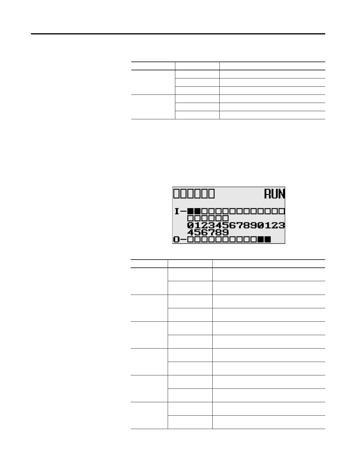
Status Indicators on the LCD
Figure 4 - Status Indicators on the LCD
FAULT off No fault detected
red flashing Application fault detected
red Controller hardware faulted
FORCE off No forces installed
amber Forces installed
amber flashing Forces installed in force files but forcing is disabled.
Status Indicators on the LCD
Indicator Color Indicates
COMM 0 off
(empty rectangle)
Not transmitting via RS-232/485 port (Channel 0)
on
(solid rectangle)
Transmitting via RS-232/485 port (Channel 0)
COMM 1 off
(empty rectangle)
Not transmitting via Ethernet port (Channel 1)
on
(solid rectangle)
Transmitting via Ethernet port (Channel 1)
COMM 2 off
(empty rectangle)
Not transmitting via RS-232 port (Channel 2)
on
(solid rectangle)
Transmitting via RS-232 port (Channel 2)
DCOMM
(1)
off
(empty rectangle)
Configured communications (Channel 0)
on
(solid rectangle)
Default communications (Channel 0)
BAT. LO off
(empty rectangle)
Battery level is acceptable
on
(solid rectangle)
Battery low
U-DISP off
(empty rectangle)
Default display mode
on
(solid rectangle)
Customized display mode
Controller LED Indicators
LED Color Indicates
CO
M
M
0
COMM1
DCOMM
BAT
.
LO
U-
DI
SP
COM
M
2

 Loading...


