EasyManuals Logo

Allen-Bradley MicroLogix 1400 User Manual

Allen-Bradley MicroLogix 1400
404 pages
To Next Page IconTo Next Page
To Previous Page IconTo Previous Page
Page #340 background imageLoading...
Page #340 background image
326 Rockwell Automation Publication 1766-UM001I-EN-P - June 2015
Appendix F MicroLogix 1400 Distributed Network Protocol (DNP3)
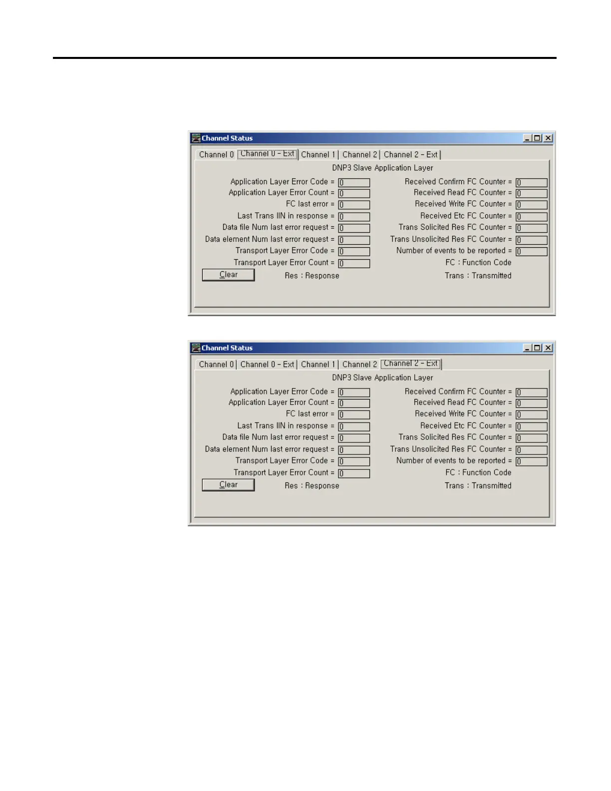
For the elements of the DNP3 Slave Application Layer diagnostic counter
CS0:55 to CS0:69 and CS2:55 to CS2:69, the counter values are available with
the structured display in RSLogix 500/RSLogix Micro software as below.
Diagnostics for Ethernet Channel (Channel 1)
This feature is supported only in MicroLogix 1400 Series B controllers.
Diagnostic Counters and Errors in DNP3 Slave subsystem for the Ethernet
channel are logged in the Data File. The data file is configured in the parameter

Table of Contents

Other manuals for Allen-Bradley MicroLogix 1400

Questions and Answers:

Question and Answer IconNeed help?

Do you have a question about the Allen-Bradley MicroLogix 1400 and is the answer not in the manual?

Allen-Bradley MicroLogix 1400 Specifications

General IconGeneral
Processor32-bit
Expansion ModulesUp to 7 expansion I/O modules
Power Supply24V DC or 120/240V AC
Programming SoftwareRSLogix 500
Communication PortsEthernet, RS-232/RS-485 combo port
Controller TypeProgrammable Logic Controller (PLC)
SeriesMicroLogix
Digital Outputs12
Analog Inputs6 (embedded)
Analog Outputs2 (embedded)
High-Speed Counter6 high-speed counters
Pulse Output2 (embedded)
Ethernet PortYes

Related product manuals