EasyManuals Logo

Allen-Bradley MicroLogix 1400 User Manual

Allen-Bradley MicroLogix 1400
404 pages
To Next Page IconTo Next Page
To Previous Page IconTo Previous Page
Page #76 background imageLoading...
Page #76 background image
62 Rockwell Automation Publication 1766-UM001I-EN-P - June 2015
Chapter 4 Communication Connections
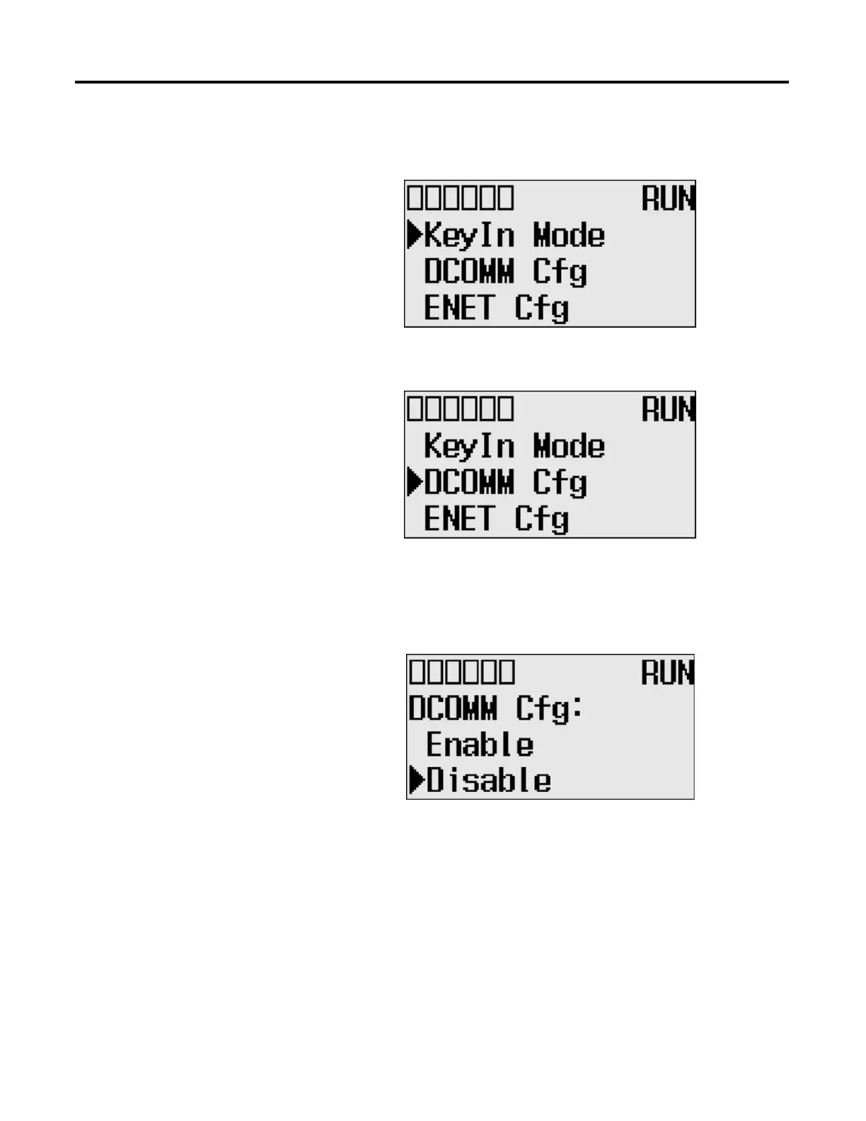
2. Press the OK key on the LCD keypad. The Advanced Settings Menu
screen is displayed.
3. Select DCOMM Cfg using the Up and Down keys, and then press the OK
key.
4. The DCOMM Configuration screen is displayed. In this example, the
current status is Disable.
The DCOMM status indicator, which is the fourth of the six indicators at
the top left of the LED display, is displayed as an empty rectangle. It means
that the communication configuration is set to a user-defined
communication mode at present.
DC
OM
M

Table of Contents

Other manuals for Allen-Bradley MicroLogix 1400

Questions and Answers:

Question and Answer IconNeed help?

Do you have a question about the Allen-Bradley MicroLogix 1400 and is the answer not in the manual?

Allen-Bradley MicroLogix 1400 Specifications

General IconGeneral
Processor32-bit
Expansion ModulesUp to 7 expansion I/O modules
Power Supply24V DC or 120/240V AC
Programming SoftwareRSLogix 500
Communication PortsEthernet, RS-232/RS-485 combo port
Controller TypeProgrammable Logic Controller (PLC)
SeriesMicroLogix
Digital Outputs12
Analog Inputs6 (embedded)
Analog Outputs2 (embedded)
High-Speed Counter6 high-speed counters
Pulse Output2 (embedded)
Ethernet PortYes

Related product manuals