EasyManuals Logo

Allen-Bradley MicroLogix 1400 User Manual

Allen-Bradley MicroLogix 1400
404 pages
To Next Page IconTo Next Page
To Previous Page IconTo Previous Page
Page #113 background imageLoading...
Page #113 background image
Rockwell Automation Publication 1766-UM001I-EN-P - June 2015 99
Using the LCD Chapter 5
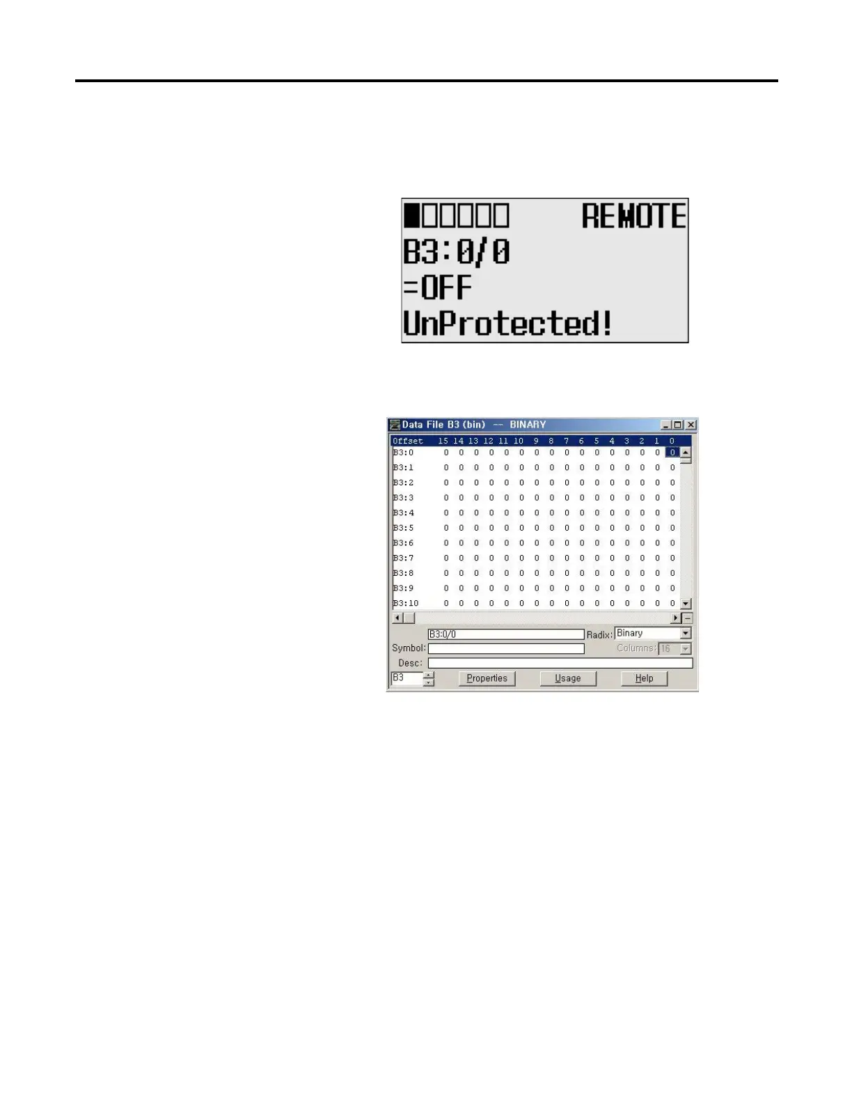
7. Press OK to apply the changes. Then, the new value OFF (0) is applied.
Note that the target bit, “0/0” in this example, is flashing. The cursor is
moved automatically to the target bit position.
You can identify this change of data value is reflected to your
RSLogix 500/RSLogix Micro programming software.
TIP
When the cursor is at the data value position, press the Down key to
change the data value of a bit from ON (1) to OFF (0). Press the Up key
to change from OFF (0) to ON (1).
After changing the data value of a target bit, press the OK key to apply
the changes or press the ESC key to discard the changes.

Table of Contents

Other manuals for Allen-Bradley MicroLogix 1400

Questions and Answers:

Question and Answer IconNeed help?

Do you have a question about the Allen-Bradley MicroLogix 1400 and is the answer not in the manual?

Allen-Bradley MicroLogix 1400 Specifications

General IconGeneral
Processor32-bit
Expansion ModulesUp to 7 expansion I/O modules
Power Supply24V DC or 120/240V AC
Programming SoftwareRSLogix 500
Communication PortsEthernet, RS-232/RS-485 combo port
Controller TypeProgrammable Logic Controller (PLC)
SeriesMicroLogix
Digital Outputs12
Analog Inputs6 (embedded)
Analog Outputs2 (embedded)
High-Speed Counter6 high-speed counters
Pulse Output2 (embedded)
Ethernet PortYes

Related product manuals