144 Rockwell Automation Publication 1766-UM001I-EN-P - June 2015
Chapter 5 Using the LCD
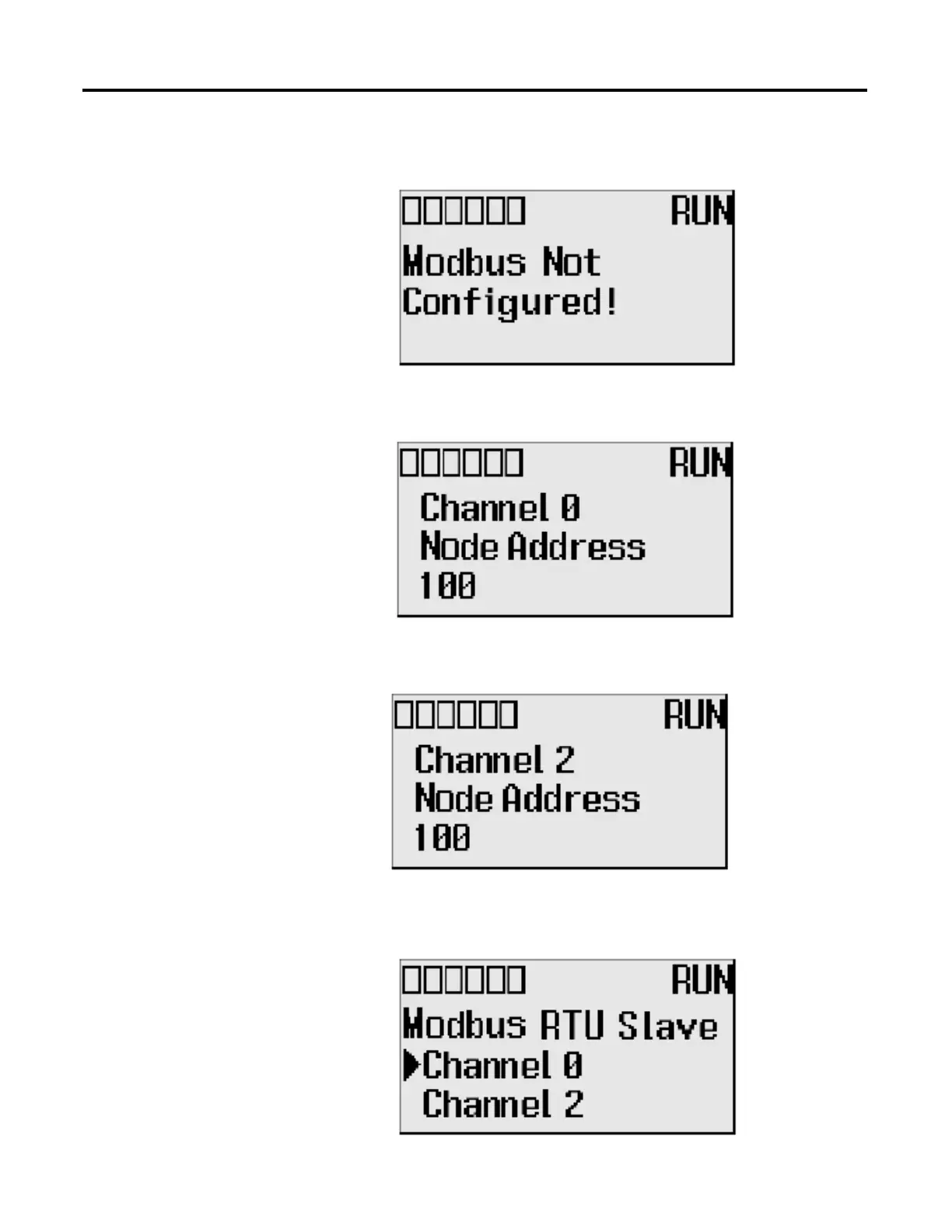
7. If the channel selected is not configured with the Modbus RTU Slave
driver, then Modbus Not Configured is displayed, as shown below.
8. If channel 0 is configured with the Modbus RTU Slave driver with node
address 100, the following screen will appear as shown.
9. If channel 2 is configured with the Modbus RTU Slave driver with node
address 100, the following screen will appear as shown.
10. The user can configure the node address for either channel by using the Up
and Down arrow keys. Once the address is changed, press OK to confirm
the change. The following screen appears.

 Loading...


