Rockwell Automation Publication 1766-UM001I-EN-P - June 2015 157
Specifications Appendix A
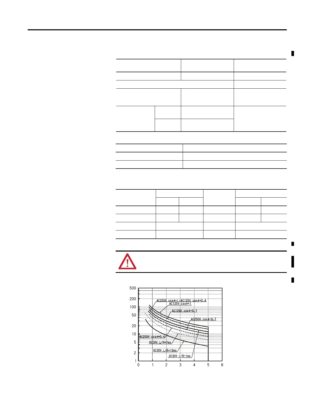
Relay Life Chart
Relay and FET Outputs
Description 1766-L32AWA/A,
1766-L32BWA/A
1766-L32BXB/A
Maximum controlled load 1440 VA 1080 VA
Maximum Continuous Current:
Current per channel and group
common
2.5 A per channel
8A max channel 8...11
common
2.5 A per channel
Current per
controller
at 150V max 28 A or total of per-point
loads, whichever is less
at 240V max 20 A or total of per-point
loads, whichever is less
Relay Outputs
Description 1766-L32AWA/A, 1766-L32BWA/A, 1766-L32BXB/A
Turn On Time/Turn Off Time 10 ms (maximum)
(1)
(1) Scan time dependent
Load current 10 mA (minimum)
Relay Contact Ratings
(1)
(1) Pilot Duty Rating (at Relay Contact Ratings): C300, R300.
Maximum Volts Amperes Amperes
Continuous
Volt-Amperes
Make Break Make Break
240V AC 7.5 A 0.75 A 2.5 A 1800 VA 180 VA
120V AC 15.0 A 1.5 A 2.5 A 1800 VA 180 VA
250V DC 0.11 A 1.0 A 28 VA
125V DC 0.22 A 1.0 A 28 VA
ATTENTION: Do not exceed the “Current per group common”
specification.
Number of operations (x 10
4
)
Switching capacity(A)

 Loading...


