262 Rockwell Automation Publication 1766-UM001I-EN-P - June 2015
Appendix F MicroLogix 1400 Distributed Network Protocol (DNP3)
• Double Bit Binary Input Config File Number
For Binary Input and Binary Output type data, you can configure Online
information of the object flag in the Configuration file. If this bit is set, the
Online bit(bit 0) in the object flag for each point is set when you read Status type
objects. You can set this information using ladder logic.
Related Configuration File:
• Binary Input Online Config File Number (In Series B)
• Binary Output Online Config File Number
For other Input type data, you can configure Class information and the object
flag information in the Configuration file. The lower 2 bits in the elements of the
Configuration files are the configuration of Class information to the relevant
objects. The upper byte of the configuration file of these objects is used to
configure the object flag. Other bits are reserved.
Two new bits are defined in MicroLogix 1400 Series B controllers.
The bit TE is used to generate an event by setting it regardless of the change of
state. This bit can be used to generate the timed events. Once this bit is set by the
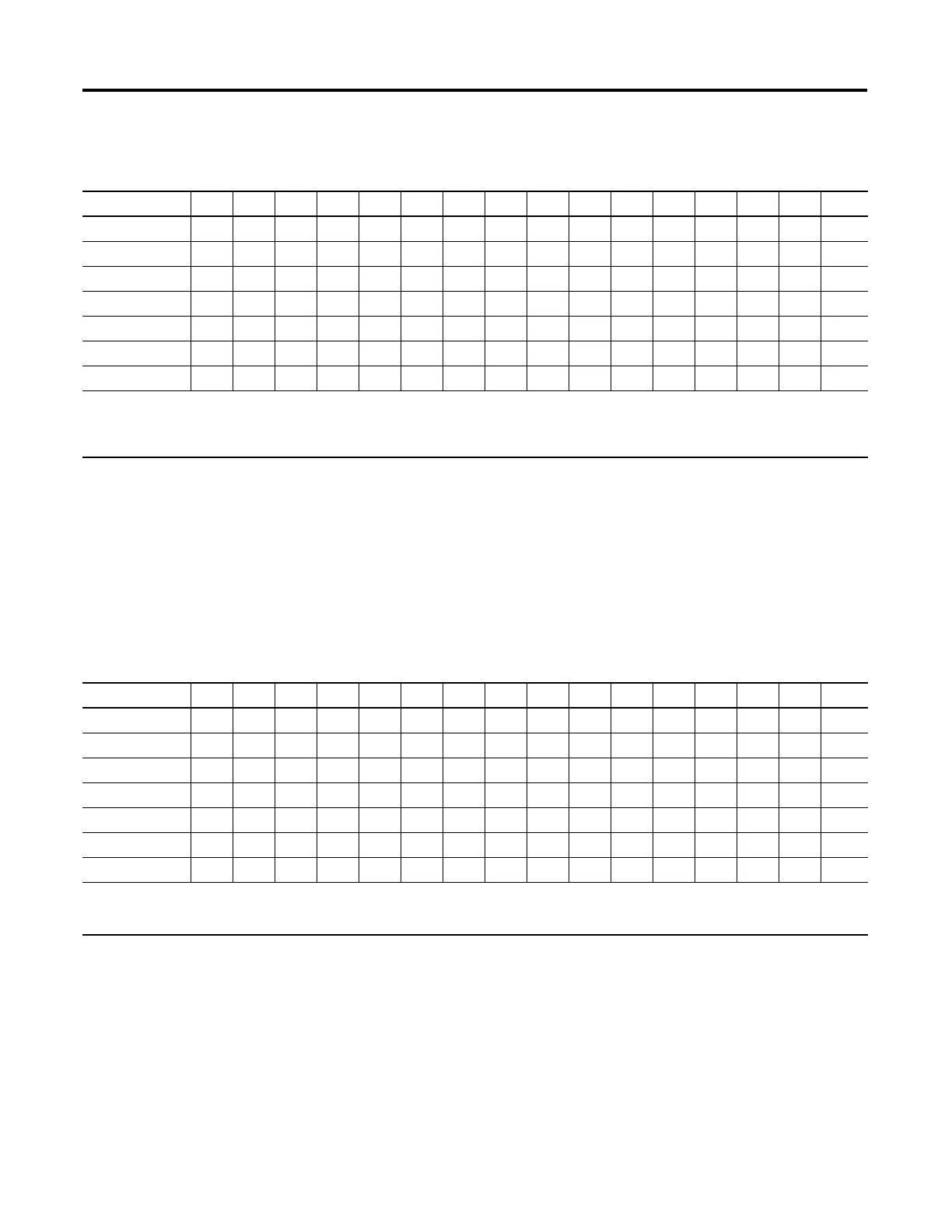
Class Information Configuration for Binary Input, Double Bit Binary Input, and Small BCD
Bit Offset 1514131211109876543210
Element 0 rrrrrrrrrrrrrrC1C0
Element 1 rrrrrrrrrrrrrrC1C0
Element 2 rrrrrrrrrrrrrrC1C0
Element 3 rrrrrrrrrrrrrrC1C0
Element 4 rrrrrrrrrrrrrrC1C0
Element 5 rrrrrrrrrrrrrrC1C0
…
r: reserved
C1/C0: Class level, 0 to 3
For Binary Input, Element_0 for data index 0 to 15
For Double-Bit Binary Input, Element _0 for data index 0 to 7
Binary Input and Binary Output Type Configuration Data File
Bit Offset 1514131211109876543210
Element 0 0000000000000000
Element 1 0000000000000000
Element 2 0000000000000000
Element 3 0000000000000000
Element 4 0000000000000000
Element 5 0000000000000000
…
0: offline
1: online
For Binary Output, Element_0 for data index 0 to 15

 Loading...


