266 Rockwell Automation Publication 1766-UM001I-EN-P - June 2015
Appendix F MicroLogix 1400 Distributed Network Protocol (DNP3)
• g1v1 - Binary Input - Packed format (default)
• g1v2 - Binary Input - With flags
Binary Input Event Objects:
• g2v0 - Binary Input Event - All Variations
• g2v1 - Binary Input Event - Without time
• g2v2 - Binary Input Event - With absolute time
• g2v3 - Binary Input Event - With relative time (default)
Related Object File Number:
• Binary Input Object File Number
Related Configuration File Number:
• Binary Input Config File Number
To generate a Binary Input Object from the DNP3 Subsystem in the controller,
you should configure Binary Input Object File Number in the DNP3 Slave
Application Layer Configuration file.
When the Binary Input Object File is configured, Index number starts from 0. 1
bit is used for 1 Index.
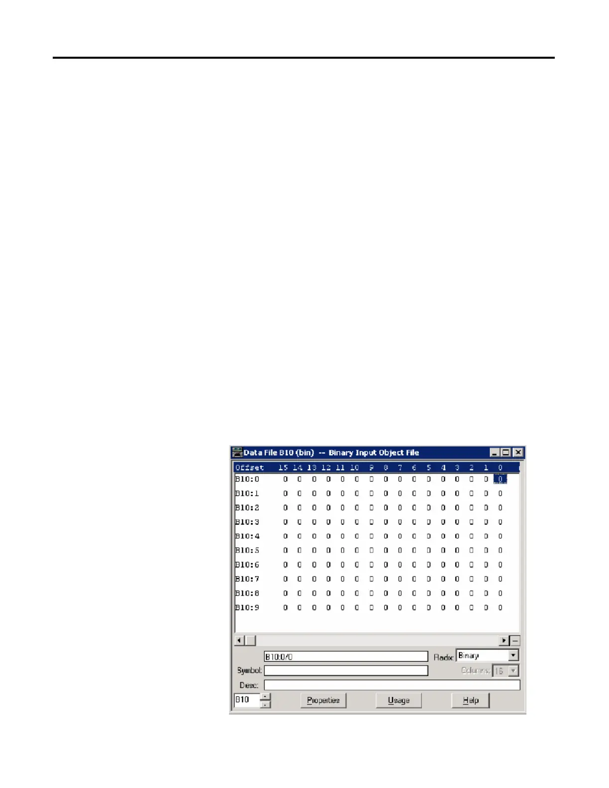
As an example, a Binary Input Object File is configured as shown below. This file
has 10 elements and 160 Binary Input points. Index 0 of the Binary Input Object
is B10:0/0, Index 1 is B10:0/1 and Index 159 is B10:9/15.

 Loading...


