Rockwell Automation Publication 1766-UM001I-EN-P - June 2015 271
MicroLogix 1400 Distributed Network Protocol (DNP3) Appendix F
• Double Bit Binary Input Object File Number
Related Configuration File Number:
• Double Bit Binary Input Config File Number
To generate a Double Bit Binary Input Object from the DNP3 Subsystem in the
controller, you should configure Double Bit Binary Input Object File Number in
the DNP3 Slave Application Layer Configuration file.
When the Double Bit Binary Input Object File is configured, the Index number
starts from 0.
2 bits are used for one Index.
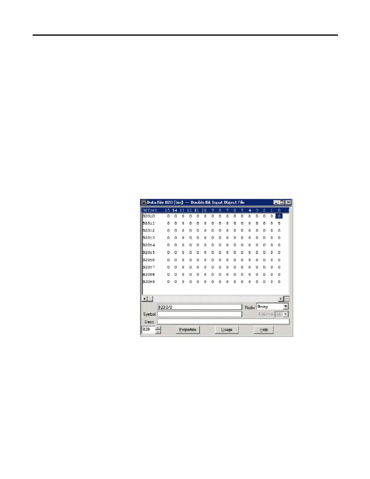
As an example, a Double Bit Binary Input Object File is shown below. This file
has 10 elements and 80 Double Bit Binary Input points. Index 0 of the Double
Bit Binary Input Object is B20:0/0 and B20:0/1, Index 1 is B20:0/2 and
B20:0/3, and Index 79 is B20:9/14 and B20:9/15.
As an example, a Double Bit Binary Input Config File is shown below. This file
has 10 elements. B39:0/0 and B39:0/1 can be configured for Class Level 0, 1, 2 or
3 for DNP3 Index 0 to 7 of the Double Bit Binary Input Object File. B39:1/0
and B39:1/1 can be configured for Class Level for DNP3 Index 8 to 15 of the
Double Bit Binary Input Object File. Default Class Level is 0. Any other bits are
reserved. So, in the example below, Class Level of Index 0 to 7 is 1(B39:0/0 and

 Loading...


