276 Rockwell Automation Publication 1766-UM001I-EN-P - June 2015
Appendix F MicroLogix 1400 Distributed Network Protocol (DNP3)
If both 16-bit Counter Object File Number and 32-bit Counter Object File
Number were configured in the DNP3 Slave Application Layer Configuration
file, the 16-bit Frozen Counter Object starting index number is 0 and the 32-bit
Frozen Counter Object starting index number of starts after the last index
number for 16-bit Frozen Counter Object. For example, if 10 elements of 16-bit
Counter Object were configured and 10 elements of 32-bit Counter Object were
configured, the index numbers will be:
• 16-bit Frozen Counter Object: From 0 to 9
• 32-bit Frozen Counter Object: From 10 to 19
When only one of the Counter Object File was configured, Index number starts
from 0 for the configured object.
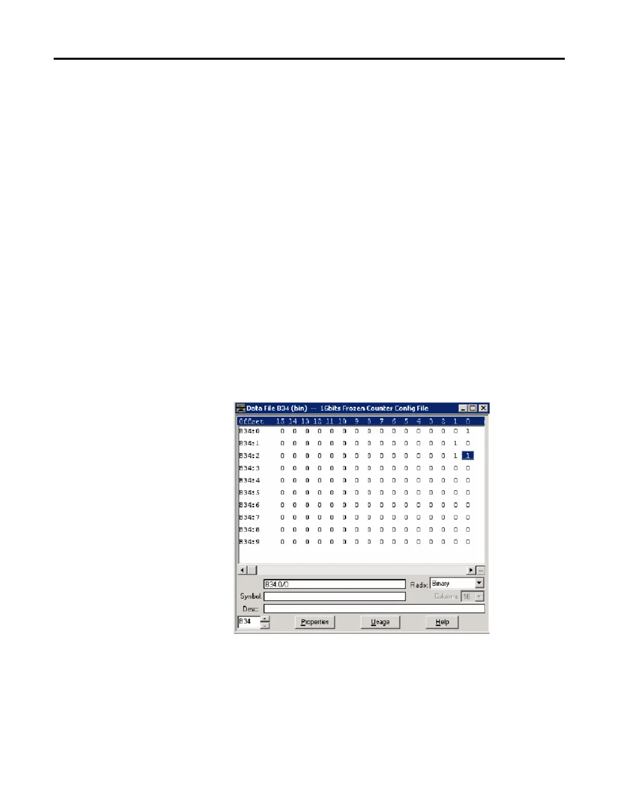
As an example, a Frozen Counter Config File is shown below. These files have 10
elements for each. B34:0/0 and B34:0/1 can be configured for Class Level 0, 1, 2
or 3 for DNP3 Index 0 of the 16 bits Frozen Counter Object File. B34:1/0 and
B34:1/1 can be configured for Class Level for DNP3 Index 1 of the Counter
Object File. Default Class Level is 0. Any other bits are reserved. So, in the
example below, for 16-bit Frozen Counter Config File, Class Level of Index 0 is
1(B34:0/0 and B34:0/1), Class Level of Index 1 is 2(B34:1/0 and B34:1/1),
Class Level of Index 2 is 3(B34:2/0 and B34:2/1), and Class Level of other
Indexes are 0.

 Loading...


