282 Rockwell Automation Publication 1766-UM001I-EN-P - June 2015
Appendix F MicroLogix 1400 Distributed Network Protocol (DNP3)
To generate Analog Output Object from the DNP3 Subsystem in the controller,
you should configure the Analog Output Object File Number in the DNP3 Slave
Application Layer Configuration file.
When only one of the Analog Output Object File is configured, Index number
starts from 0 for the configured object. 1 word is used for 1 Index of 16-bit
Analog Output Object, 1 double word is used for 1 Index of 32-bit Analog
Output Object, and 1 short float is used for 1 Index of Short Floating Point
Analog Output Object.
If the 16-bit Analog Output Object File Number, 32-bit Analog Output Object
File Number, and Short Floating Point Analog Output Object File Number are
configured in the DNP3 Slave Application Layer Configuration file, the starting
index number of 16-bit Analog Output Object is 0 and the starting index number
of 32-bit Analog Output Object starts from the last index number of 16-bit
Analog Output Object.
For example, if 10 elements of 16-bit Analog Output Object are configured, 10
elements of 32-bit Analog Output Object, and 10 elements of Short Floating
Point Analog Output Object are configured, the index numbers will be:
• 16-bit Analog Output Object: From 0 to 9
• 32-bit Analog Output Object: From 10 to 19
• Short Floating Point Analog Output Object: From 20 to 29
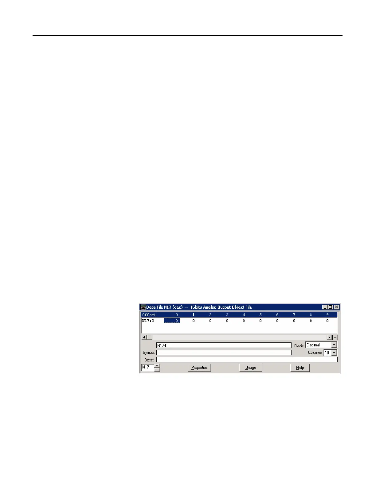
As an example, 16-bit, 32-bit and Short Floating Point Analog Output Object
Files are configured as below. Data File N17 has 10 elements, L18 has 10 elements
and F19 has 10 elements accordingly. A total of 30 Analog Output Object index
are configured. Index 0 of the Analog Output Object is N17:0, Index 10 is L18:0,
Index 20 is F19:0 and Index 29 is F19:9.

 Loading...


