EasyManuals Logo

Allen-Bradley MicroLogix 1400 User Manual

Allen-Bradley MicroLogix 1400
404 pages
To Next Page IconTo Next Page
To Previous Page IconTo Previous Page
Page #68 background imageLoading...
Page #68 background image
54 Rockwell Automation Publication 1766-UM001I-EN-P - June 2015
Chapter 3 Wire Your Controller
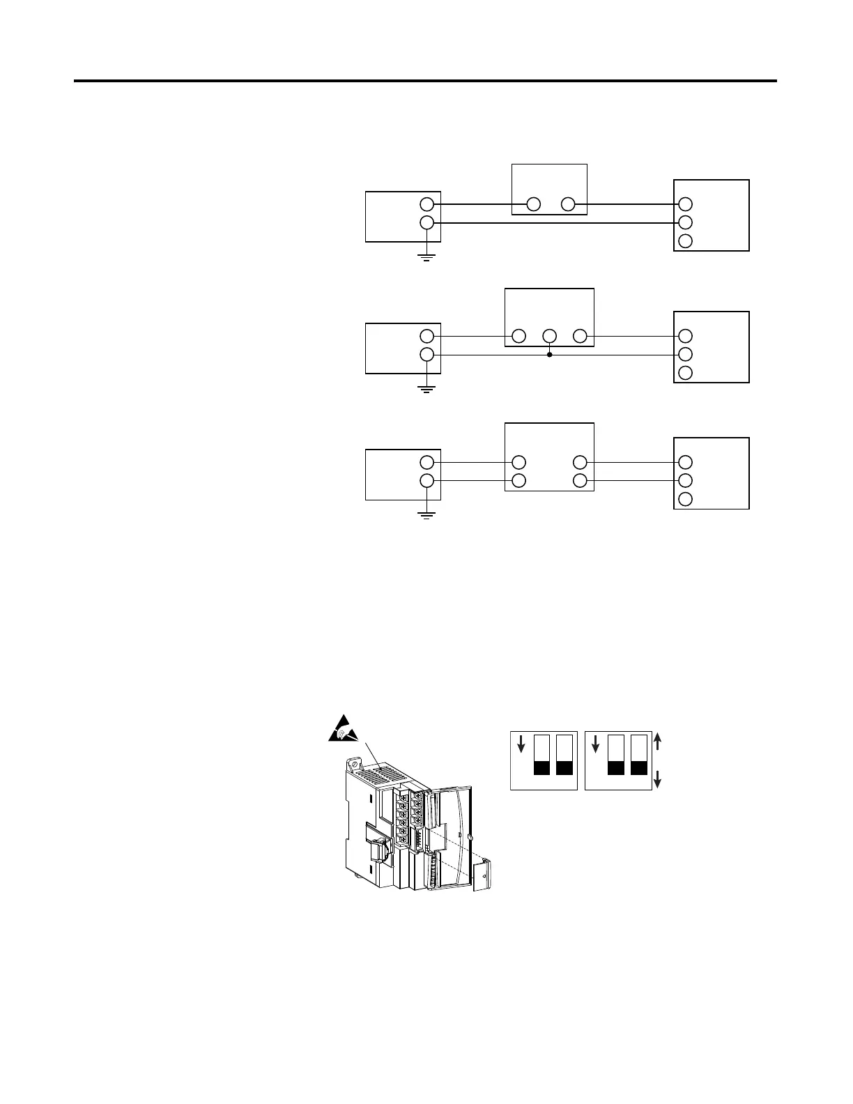
Figure 30 - Single-ended Sensor/Transmitter Types
1762-IF4 Input Type Selection
Select the input type, current or voltage, using the switches located on the
module’s circuit board and the input type/range selection bits in the
Configuration Data File. Refer to MicroLogix 1400 Programmable Controllers
Instruction Set Reference Manual, publication 1766-RM001. You can access the
switches through the ventilation slots on the top of the module.
+
+
-
-
+
-
+
-
IN +
IN -
COM
+
-
IN +
IN -
COM
+
-
IN +
IN -
COM
Power
Supply
(1)
Transmitter
Transmitter
Transmitter
Supply
Supply
Signal
Signal
Module
Module
Module
2-Wire Transmitter
3-Wire Transmitter
4-Wire Transmitter
Power
Supply
(1)
Power
Supply
(1)
(1) All power supplies rated N.E.C. Class 2.
1
Ch0 Ch1 Ch2 Ch3
ON
2 1
ON
2
Current (ON Default)
Voltage (OFF)
Switch Location

Table of Contents

Other manuals for Allen-Bradley MicroLogix 1400

Questions and Answers:

Question and Answer IconNeed help?

Do you have a question about the Allen-Bradley MicroLogix 1400 and is the answer not in the manual?

Allen-Bradley MicroLogix 1400 Specifications

General IconGeneral
Processor32-bit
Expansion ModulesUp to 7 expansion I/O modules
Power Supply24V DC or 120/240V AC
Programming SoftwareRSLogix 500
Communication PortsEthernet, RS-232/RS-485 combo port
Controller TypeProgrammable Logic Controller (PLC)
SeriesMicroLogix
Digital Outputs12
Analog Inputs6 (embedded)
Analog Outputs2 (embedded)
High-Speed Counter6 high-speed counters
Pulse Output2 (embedded)
Ethernet PortYes

Related product manuals