EasyManuals Logo

Allen-Bradley MicroLogix 1400 User Manual

Allen-Bradley MicroLogix 1400
404 pages
To Next Page IconTo Next Page
To Previous Page IconTo Previous Page
Page #83 background imageLoading...
Page #83 background image
Rockwell Automation Publication 1766-UM001I-EN-P - June 2015 69
Communication Connections Chapter 4
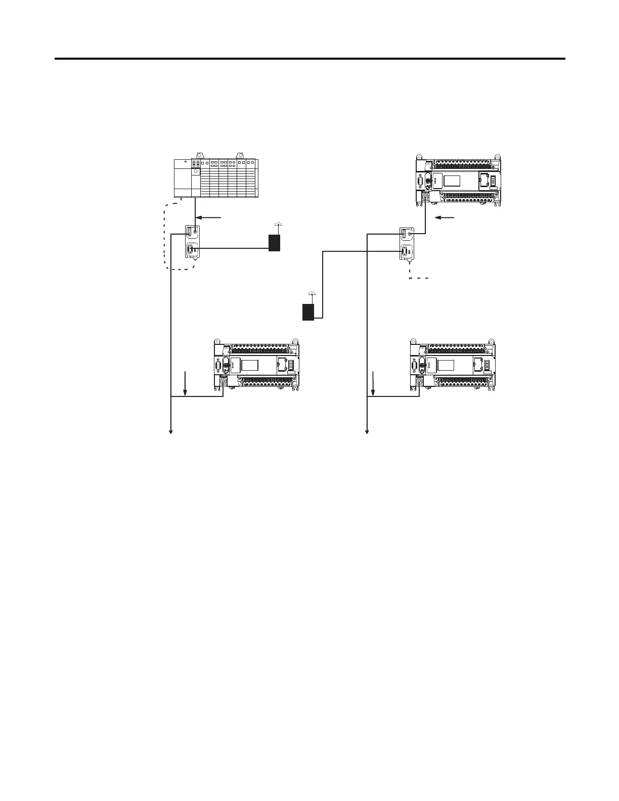
DF1 Half-Duplex Master-Slave Network
Use the following diagram for DF1 Half-Duplex Master-Slave protocol without
hardware handshaking.
(1) DB-9 RS-232 port
(2) mini-DIN 8 RS-232 port
(3) RS-485 port
(4) Series C or later cables are required for Class I Div 2 applications.
(1)
(1)
(2)
(2)
(3)
(3)
SLC 5/03
processor
MicroLogix 1400
MicroLogix 1400
MicroLogix
1400
CH0
CH0
CH0
CH0
1761-CBL-AP00 or 1761-CBL-PM02
(4)
1761-CBL-AM00 or 1761-CBL-HM02
(4)
DF1
Master
DF1 Slave
DF1 Slave
straight 9-25 pin cable
straight 9-25
pin cable
radio modem
or lease line
radio
modem or
lease line
AIC+
RS-485 DF1
Half-Duplex
DF1 Slave
1763-NC01 (daisy chain) to AIC+
(4)
AIC+
24V DC power (User Supplied)
1763-NC01 (daisy chain) to AIC+
(4)
44595
RS-485 DF1
Half-Duplex

Table of Contents

Other manuals for Allen-Bradley MicroLogix 1400

Questions and Answers:

Question and Answer IconNeed help?

Do you have a question about the Allen-Bradley MicroLogix 1400 and is the answer not in the manual?

Allen-Bradley MicroLogix 1400 Specifications

General IconGeneral
Processor32-bit
Expansion ModulesUp to 7 expansion I/O modules
Power Supply24V DC or 120/240V AC
Programming SoftwareRSLogix 500
Communication PortsEthernet, RS-232/RS-485 combo port
Controller TypeProgrammable Logic Controller (PLC)
SeriesMicroLogix
Digital Outputs12
Analog Inputs6 (embedded)
Analog Outputs2 (embedded)
High-Speed Counter6 high-speed counters
Pulse Output2 (embedded)
Ethernet PortYes

Related product manuals