Publication 1766-RM001A-EN-P - October 2008
Relay-Type (Bit) Instructions 173
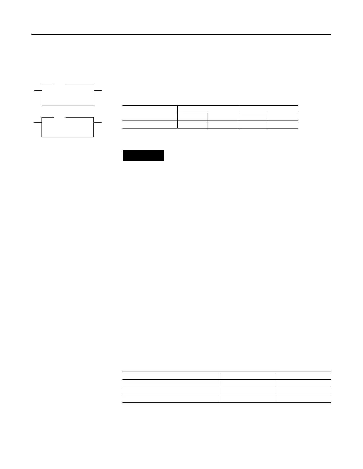
OSR - One Shot Rising
OSF - One Shot Falling
Instruction Type: output
Use the OSR and OSF instructions to trigger an event to occur one time.
These instructions trigger an event based on a change of rung state, as
follows:
• Use the OSR instruction when an event must start based on the
false-to-true (rising edge) change of state of the rung.
• Use the OSF instruction when an event must start based on the
true-to-false (falling edge) change of state of the rung.
These instructions use two parameters, Storage Bit and Output Bit.
• Storage Bit - This is the bit address that remembers the rung state
from the previous scan.
• Output Bit - This is the bit address which is set based on a
false-to-true (OSR) or true-to-false (OSF) rung transition. The Output
Bit is set for one program scan.
To re-activate the OSR, the rung must become false. To re-activate the
OSF, the rung must become true.
OSR
One Shot Rising
Storage Bit B3:0/0
Output Bit B3:0/1
OSR
OSF
One Shot Falling
Storage Bit B3:0/0
Output Bit B3:0/1
OSF
Execution Time for the OSR and OSF Instructions
Controller OSR - When Rung Is: OSF - When Rung Is:
True False True False
MicroLogix 1400 1.3766 µs 1.3724 µs 1.3672 µs 2.0952 µs
TIP
The OSR instruction for the MicroLogix 1400 does not provide the same
functionality as the OSR instruction for the MicroLogix 1000 and SLC 500
controllers. For the same functionality as the OSR instruction for the
MicroLogix 1000 and SLC 500 controllers, use the ONS instruction.
OSR Storage and Output Bit Operation
Rung State Transition Storage Bit Output Bit
false-to-true (one scan) bit is set bit is set
true-to-true bit is set bit is reset
true-to-false and false-to-false bit is reset bit is reset
efesotomasyon.com - Allen Bradley,Rockwell,plc,servo,drive

 Loading...


