Publication 1766-RM001A-EN-P - October 2008
Sequencer Instructions 295
• Source - The source operand is a constant or address of the value
used to fill the currently available position sequencer file. The
address level of the source must match the sequencer file. If file is a
word type, then source must be a word type. If file is a long word
type, then source must be a long word type. The data range for the
source is from -32,768…32,767 (word) or
-2,147,483,648…2,147,483,647 (long word).
• Control - This is a control file address. The status bits, stack length,
and the position value are stored in this element. The control
element consists of 3 words:
• Length - The length operand contains the number of steps in the
sequencer file (this is also the length of source if it is a file data
type). The length of the sequencer can range from 1…256.
• Position - This is the current location or step in the sequencer file
(as well as source if it is a file data type). It determines the next
location in the stack to receive the value or constant found in
source. Position is a component of the control register. The position
can range from 0…255.
Addressing Modes and File Types can be used as shown in the following
table:
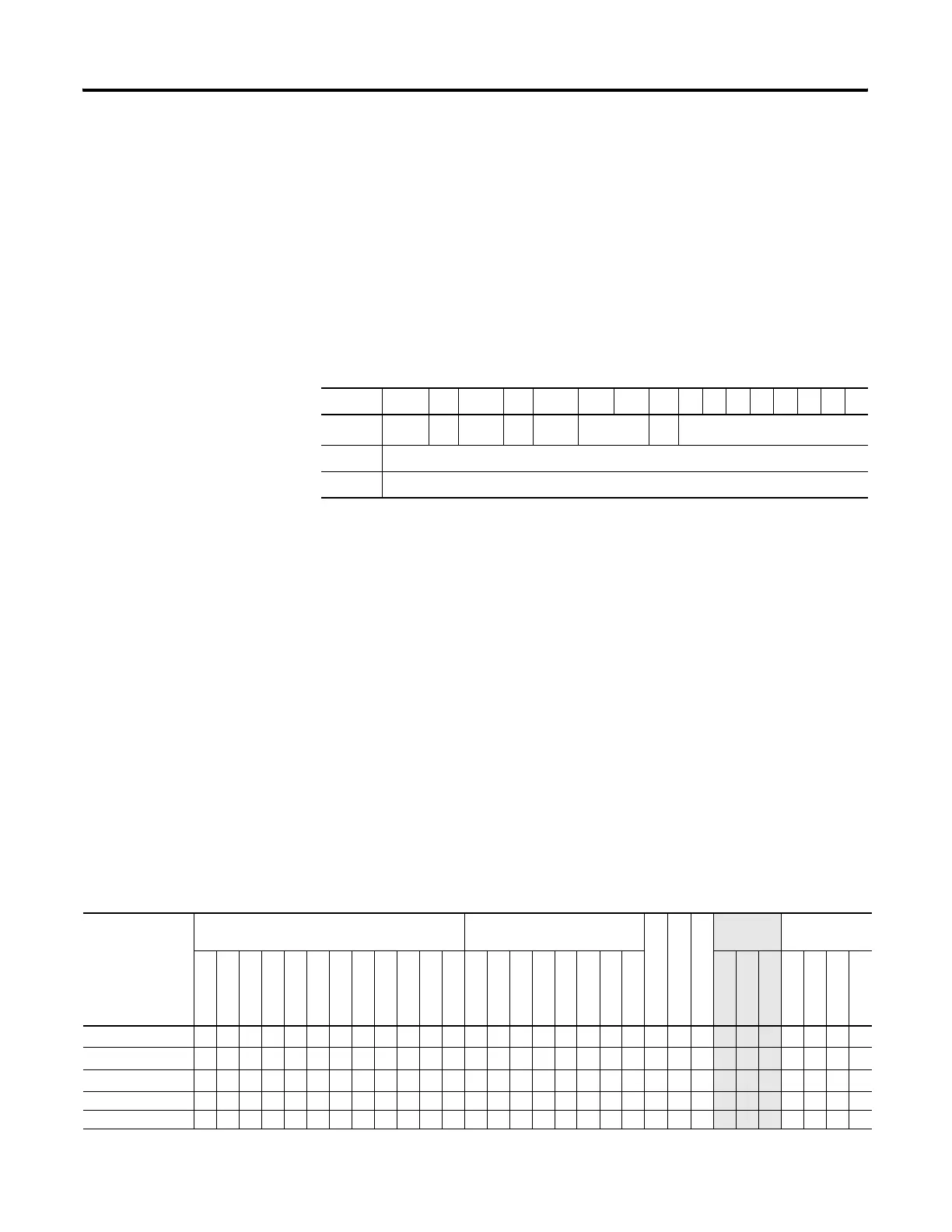
15 1413 1211 10 9 8 76543210
Word 0
EN
(1)
(1) EN - Enable Bit is set by a false-to-true rung transition and indicates that the instruction is enabled.
--
DN
(2)
(2) DN - Done Bit is set after the instruction has operated on the last word in the sequencer file. It is reset on the next
false-to-true rung transition after the rung goes false.
--
ER
(3)
(3) ER - Error Bit is set when the controller detects a negative position value, or a negative or zero length value. When the
ER bit is set, the minor error bit (S2:5/2) is also set.
not used FD not used
Word 1 Length - contains the index of the last element in the sequencer reference file
Word 2 Position - the current position in the sequence
SQL Instruction Valid Addressing Modes and File Types
For definitions of the terms used in this table see Using the Instruction Descriptions on page 92.
Parameter
Data Files Function Files
CS - Comms
IOS - I/O
DLS - Data Log
Address
Mode
(1)
Address Level
O
I
S
B
T, C, R
N
F
ST
L
MG, PD
RI/RIX
PLS
RTC
HSC
PTOX, PWMX
STI
EII
BHI
MMI
LCD
Immediate
Direct
Indirect
Bit
Word
Long Word
Element
File
(2)
•••• •• • •••
Source
(2)
•••• •• • • •••
Control
(3)
• •
Length
• •
Position
• •
efesotomasyon.com - Allen Bradley,Rockwell,plc,servo,drive

 Loading...


