Publication 1766-RM001A-EN-P - October 2008
432 Communications Instructions
Example 5 - Configuring an Ethernet/IP Message
This section describes how to configure a local message when you are
use Ethernet communication channel 1 of the MicroLogix 1400.
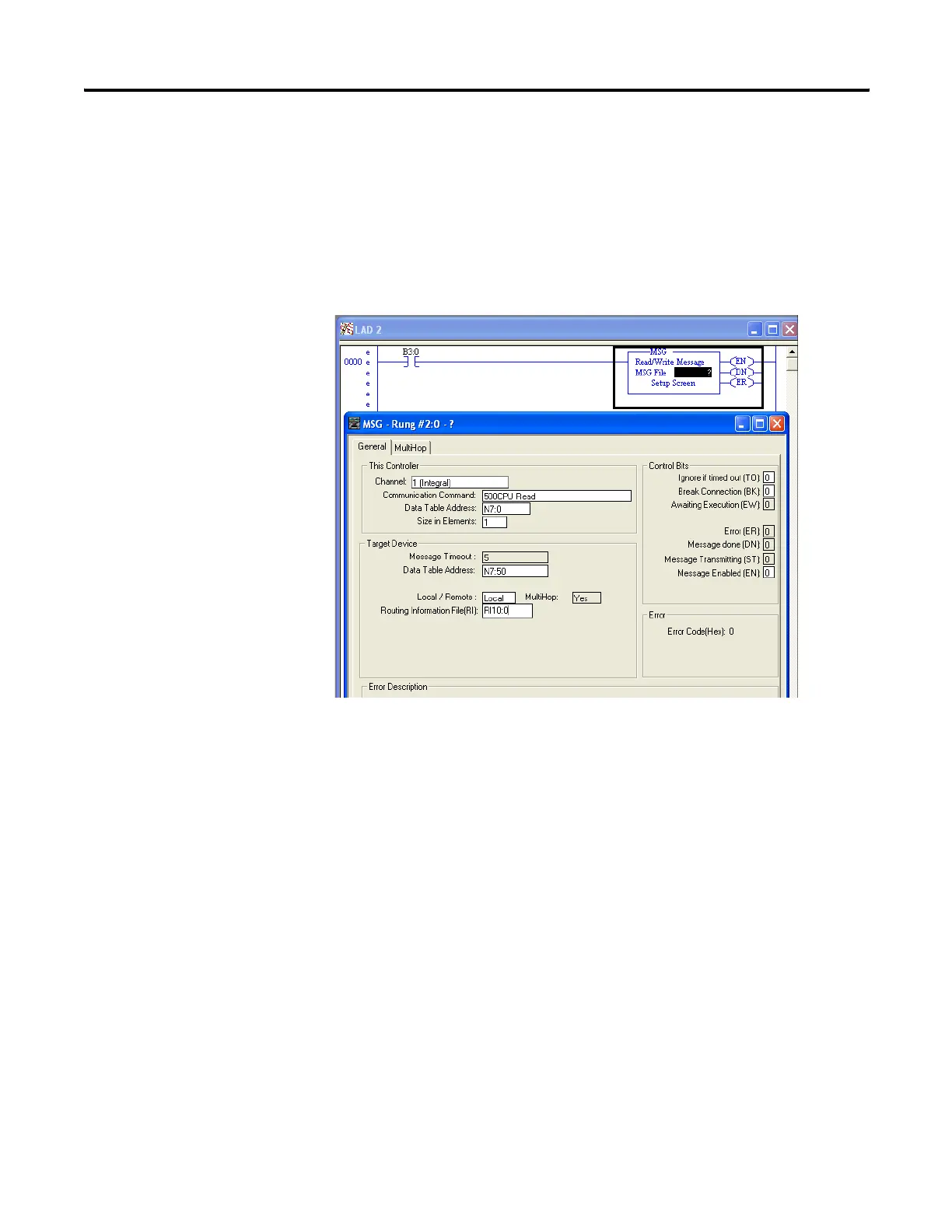
Message Setup Screen
Rung 0 shows a standard RSLogix 500/RSLogix Micro message (MSG)
instruction preceded by conditional logic.
1. Access the message setup screen by double-clicking Setup Screen.
2. The RSLogix 500/RSLogix Micro Message Setup Screen appears.
This screen is used to setup or monitor message parameters for
“This Controller”, “Target Device”, and “Control Bits”. Descriptions
of each of these sections follow.
efesotomasyon.com - Allen Bradley,Rockwell,plc,servo,drive

 Loading...


