EasyManuals Logo

Allen-Bradley MicroLogix 1400 User Manual

Allen-Bradley MicroLogix 1400
694 pages
To Next Page IconTo Next Page
To Previous Page IconTo Previous Page
Page #438 background imageLoading...
Page #438 background image
Publication 1766-RM001A-EN-P - October 2008
436 Communications Instructions
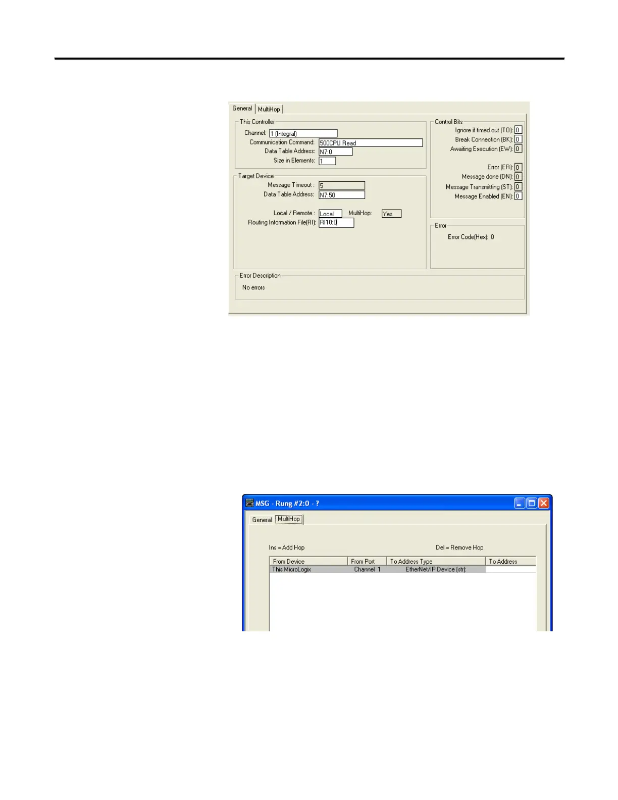
In this example, the controller reads 10 elements from the target's N7 file,
starting at word N7:50 using 500CPU Read command. The 10 words are
placed in the controller's integer file starting at word N7:0. If 33 seconds
elapse before the message completes, error bit MG11:0/ER is set,
indicating that the message timed out.
If the target device is another MicroLogix 1400, a SLC 5/05, a PLC-5E or a
controller connected to Ethernet via a 1761-NET-ENI, then simply enter in
the device’s IP address in the “To Address” column as shown below under
the MultiHop tab.
For more information on routing through a ControlLogix gateway, refer to
Configuring a Multi-hop Remote Message on EtherNet/IP Communication
Channel on page 445.
efesotomasyon.com - Allen Bradley,Rockwell,plc,servo,drive

Table of Contents

Other manuals for Allen-Bradley MicroLogix 1400

Questions and Answers:

Question and Answer IconNeed help?

Do you have a question about the Allen-Bradley MicroLogix 1400 and is the answer not in the manual?

Allen-Bradley MicroLogix 1400 Specifications

General IconGeneral
Processor32-bit
Expansion ModulesUp to 7 expansion I/O modules
Power Supply24V DC or 120/240V AC
Programming SoftwareRSLogix 500
Communication PortsEthernet, RS-232/RS-485 combo port
Controller TypeProgrammable Logic Controller (PLC)
SeriesMicroLogix
Digital Outputs12
Analog Inputs6 (embedded)
Analog Outputs2 (embedded)
High-Speed Counter6 high-speed counters
Pulse Output2 (embedded)
Ethernet PortYes

Related product manuals