Publication 1766-RM001A-EN-P - October 2008
Protocol Configuration 609
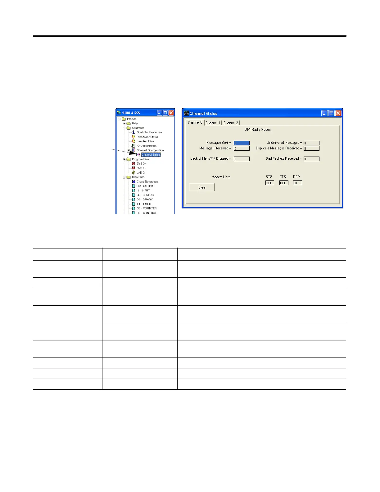
DF1 Radio Modem Channel Status
Channel Status data is stored in the Communication Status Function File.
Viewing Channel Status for DF1 Radio Modem
Communication Status Function DF1 Radio Modem Channel Status
Status Field
Diagnostic File Location
(1)
(1) x equals Channel number
Definition
Messages Sent CSx:10 The total number of DF1 messages sent by the processor (including
message retries)
Messages Received CSx:11 The number of messages received with no errors
Lack of Memory CSx:17 The number of times the processor could not receive a message because
it did not have available memory
Undelivered Messages CSx:12 The number of messages that could not be sent by the processor due to
bad modem handshake signals
Duplicate Messages
Received
CSx:18 The number of times the processor received a message packet identical
to the previous message packet
Bad Packet Received CSx:16 The number of data packets received by the processor that had bad
checksum or were truncated
RTS (Request to Send) CSx:9/1 The status of the RTS handshaking line (asserted by the processor)
CTS (Clear to Send) CSx:9/0 The status of the CTS handshaking line (received by the processor)
DCD (Data Carrier Detect) CSx:9/3 Reserved
Double-click the Channel Status Icon
Located beneath the Configuration
icon to bring up the Channel Status
screen.
efesotomasyon.com - Allen Bradley,Rockwell,plc,servo,drive

 Loading...


