EasyManuals Logo

Allen-Bradley MicroLogix 1400 User Manual

Allen-Bradley MicroLogix 1400
694 pages
To Next Page IconTo Next Page
To Previous Page IconTo Previous Page
Page #74 background imageLoading...
Page #74 background image
Publication 1766-RM001A-EN-P - October 2008
72 Function Files
61 - Function Code 1 Message Counter
62 - Function Code 2 Message Counter
63 - Function Code 3 Message Counter
64 - Function Code 4 Message Counter
65 - Function Code 5 Message Counter
66 - Function Code 6 Message Counter
67 - Function Code 8 Message Counter
68 - Function Code 15 Message Counter
69 - Function Code 16 Message Counter
Modbus RTU Master Diagnostic Counters Block (Data Link Layer)
Word Bit Description
6 - Diagnostic Counters Category Identifier Code (always 2)
7 - Length (always 30)
8 - Format Code (always 9)
90CTS
1RTS
2 Reserved
3 Reserved
4…15 Reserved
10 - Total Message Packets Sent
11 - Reserved
12 - Total Message Packets Received
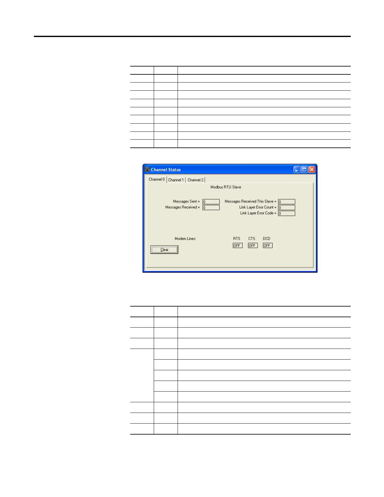
Modbus RTU Slave Diagnostic Counters Block (Presentation Layer)
Word Bit Description
efesotomasyon.com - Allen Bradley,Rockwell,plc,servo,drive

Table of Contents

Other manuals for Allen-Bradley MicroLogix 1400

Questions and Answers:

Question and Answer IconNeed help?

Do you have a question about the Allen-Bradley MicroLogix 1400 and is the answer not in the manual?

Allen-Bradley MicroLogix 1400 Specifications

General IconGeneral
Processor32-bit
Expansion ModulesUp to 7 expansion I/O modules
Power Supply24V DC or 120/240V AC
Programming SoftwareRSLogix 500
Communication PortsEthernet, RS-232/RS-485 combo port
Controller TypeProgrammable Logic Controller (PLC)
SeriesMicroLogix
Digital Outputs12
Analog Inputs6 (embedded)
Analog Outputs2 (embedded)
High-Speed Counter6 high-speed counters
Pulse Output2 (embedded)
Ethernet PortYes

Related product manuals