4-2 | Model 900 ADA / Model 930 Sulfur Pit Analyzers
Introduction to the User Interface
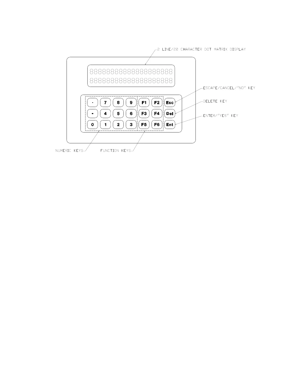
Figure 4-1 illustrates the layout of the analyzer User Interface.
User Interface Components
The User Interface is made up of two areas:
• Display area
Consists of two lines, each capable of displaying up to 20 alphanumer-
ic characters. The information displayed depends on the current op-
eration mode. Messages and other information displayed is discussed
in “Messages/Information Displayed on the User Interface.”
- The top line displays the current mode of operation, or a prompt
for further keypad input.
During normal operating conditions in RUN mode, the top line
displays the names of the outputs. When operating in CALibration
or ConFiGuration mode, the mode of operation (CAL or CFG) is
also displayed.
- The bottom line displays the results of the outputs.
During normal operating conditions in RUN mode, the bottom
line continually displays the value of each output parameter being
monitored/controlled by the analyzer.
Depending on the operation mode or the command entered, other
information can also be displayed on the bottom line.
Figure 4-1.
User Interface layout.