Installation and Start-Up | 3-27
Start-Up and Verication
This section describes equipment and controls on the analyzer system that
require adjustments and settings before, during, and after power-up.
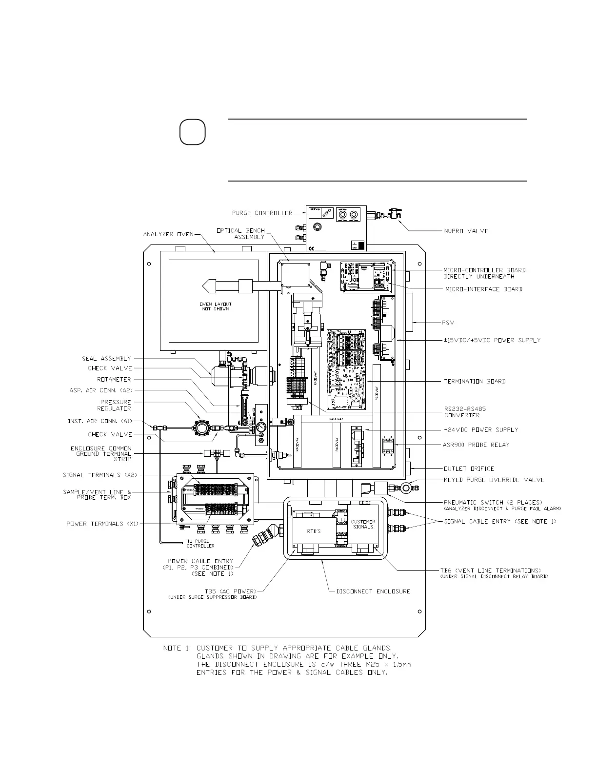
Figure 3-9 illustrates the locations of analyzer equipment and con-
trols that require adjustments for a typical Zone 1 analyzer layout.
Refer to Final “As Built” drawings for your system in the analyzer
Documentation Package.
NOTE
Figure 3-9.
Model 900/930 Zone 1
Analyzer overall
component layout.