User Manual – Rev BE AMETEK Programmable Power
MX Series 11
List of Figures
Figure 2-1: Voltage / Current Rating Chart for 150/300 V AC Ranges. ..................................................... 27
Figure 2-2: Voltage / Current Rating Chart for 150/300 V AC Ranges – Max Rating. .................................. 27
Figure 2-3 -HF Option Voltage Frequency Rating 300V range .................................................................. 38
Figure 2-4 -HF Option Voltage Frequency Rating 150V range .................................................................. 38
Figure 2-5 MX Output Filter Option Schematic ....................................................................................... 43
Figure 2-6 MX45 Output Noise 10 KHz – 1 MHz ..................................................................................... 44
Figure 2-7 MX45 Output Noise 10 KHz - 1 MHz with Optional Filter .......................................................... 45
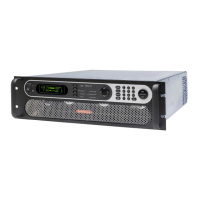
Figure 3-1: The MX45 Power Source .................................................................................................... 48
Figure 3-2: Location of AC Input and Chassis Ground Connection - Front View, Access Panel Removed ....... 50
Figure 3-3: MX Series AC Input Connection Diagram (Rear view) ............................................................ 52
Figure 3-4: Rear Panel ....................................................................................................................... 55
Figure 3-5: External Sense Cable Shield Connection to Chassis Ground .................................................... 57
Figure 3-6: Location of Output Terminals (Front view) ........................................................................... 60
Figure 3-7: MX 22.5-1, MX30-1 / MX45-1 Output Wiring (Rear view) ....................................................... 61
Figure 3-8: MX 22.5-3, MX30-3 / MX45-3 Output Wiring (rear view) ........................................................ 63
Figure 3-9: MX60, MX60-MB, MX90 or MX90-MB Output Wiring (rear view) ............................................. 65
Figure 3-10: Two MX's in Clock and Lock Mode Output Wiring (rear view) ................................................ 66
Figure 3-11: MX135 or MX135-MB Output Wiring (Rear view) ................................................................. 68
Figure 3-12: Three MX's in Clock and Lock mode - Output Wiring (rear view)............................................ 69
Figure 3-13: MX180, MX225 or MX270 Output Wiring (rear view) ........................................................... 71
Figure 3-14: Ship kit Terminal Block Dimensions ................................................................................... 73
Figure 3-15: RS232C Cable for PC Connection Wiring Diagram – MX without USB. ..................................... 78
Figure 3-16: USB Connector Pin Orientation.......................................................................................... 79
Figure 3-17: LAN Interface Connector ................................................................................................. 80
Figure 3-18: Emergency Switch (ES Option) Shutoff Interconnect on -MB systems. ................................... 81
Figure 3-19: SLAVE and ESTOP interconnect at the rear panel ................................................................ 82
Figure 3-20: Multi-Cabinet DIP Switch Location and Setting .................................................................... 83
Figure 3-21: Functional Test Setup. ..................................................................................................... 90
Figure 3-22: 7003-416-1 Output Junction Box ...................................................................................... 94
Figure 3-23: 7003-424-1 Output Noise Filter Box. ................................................................................. 95
Figure 3-24: 7003-426-1 Output Fuse Box ........................................................................................... 97
Figure 4-1. Status and Fault LEDs (MX45 front panel shown) ................................................................ 100
Figure 4-2: Shuttle Knob .................................................................................................................. 101
Figure 4-3: FUNCTION Keypad ......................................................................................................... 102
Figure 4-4: Entering Values from the Decimal Keypad .......................................................................... 104
Figure 4-5: Cursor UP Key Movement ................................................................................................ 104
Figure 4-6: Cursor DOWN Key Movement ........................................................................................... 105
Figure 4-7: Main Menu 1 Screen ........................................................................................................ 106
Figure 4-8: Menu 1 through 3 ........................................................................................................... 107
Figure 4-9: PROGRAM Menu ............................................................................................................. 113
Figure 4-10: MEASUREMENTS Screen, Single Phase and Three Phase Modes .......................................... 116
Figure 4-11: HARMONICS/TRACE ANALYSIS Screen ............................................................................. 119
Figure 4-12: TRANSIENTS Menu ........................................................................................................ 123
Figure 4-13: VOLTAGE SURGE/SAG SETUP Screen ............................................................................... 124
Figure 4-14: VOLTAGE SWEEP/STEP SETUP Screen ............................................................................. 127
Figure 4-15: FREQUENCY SWEEP/STEP SETUP Screen .......................................................................... 129
Figure 4-16 VOLTAGE/FREQUENCY SWEEP/STEP SETUP Screen ........................................................... 131
Figure 4-17:START/VIEW TRANSIENT SEQUENCE Screen ..................................................................... 132
Figure 4-18: WAVEFORMS Menu ........................................................................................................ 133
Figure 4-19: APPLICATIONS Menus.................................................................................................... 137
Figure 4-20: SETUP REGISTERS Menu ................................................................................................ 138
Figure 4-21: UTILITY Menus ............................................................................................................. 139
Figure 4-22: GPIB/RS232 SETUP Menu .............................................................................................. 143
Figure 4-23: VOLTAGE/CURRENT CONTROL SETUP Menu ..................................................................... 145
Figure 4-24: INITIAL SETUP Menus .................................................................................................... 147
Figure 4-25: LIMIT SETUP Menu ........................................................................................................ 149
Figure 4-26: CONFIGURATION SETUP Menus ...................................................................................... 150
Figure 4-27: OUTPUT IMPEDANCE Menu ............................................................................................. 154
Figure 4-28: MEASUREMENT CAL FACTORS Menu (Series I only) ........................................................... 155
Figure 4-29: MEASUREMENT CAL FACTORS Menu (Series II only) .......................................................... 155
Figure 4-30: OUTPUT CAL FACTORS Menu (Series I only) ..................................................................... 157
Figure 4-31: OUTPUT CAL FACTORS Menu (Series II only) .................................................................... 157
 Loading...

