User Manual – Rev BE AMETEK Programmable Power
MX Series 81
3.7.8 ES Option - Emergency Switch Interconnect for –MB systems – BNC
Except for MX units shipped January 2017 and later, an optional BNC connector
is located on the rear panel for connecting multiple chassis, each having a
controller and an emergency shut off switch (-ES option). This connection is
required to create an OR-ed operation of more than one –ES switch. (The newer
MX units with the emergency shutoff option are designed with the shutdown
signal built into the system interface cable, thus eliminating the need for a BNC
cable).
This connector is only present on MX-MB systems (except as mentioned) with
the –ES option. If present, a suitable BNC cable should be used to connect the
emergency shut off signal between chassis. This connector is labeled as follows:
"Caution: BNC cable must be connected for system Emergency
Shut-Down"
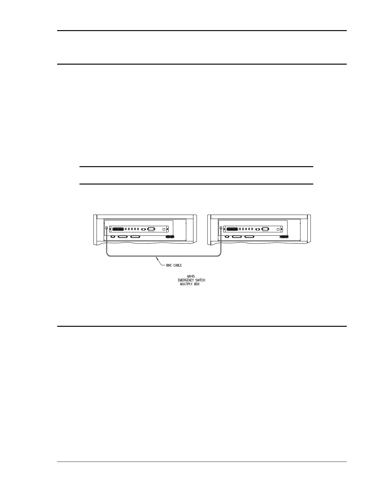
See figure below for an illustration of a MX90-MB-ES interconnect.
Figure 3-18: Emergency Switch (ES Option) Shutoff Interconnect on -MB systems.
3.7.9 Master Select and Emergency Stop Switch Interconnect for –MB systems
A single row six pole terminal block (Figure 3-19) is located on the rear panel
for remote-control of Master / Auxiliary configurations and Emergency Stop.
SLAVE and SCOM are used to remote-control each MX135 system to configure
for Master or Auxiliary operation. When 24V DC is applied the SLAVE and SCOM
the system is configured in AUXILIRIY operation. When 24V DC is removed, the
unit operates in MASTER mode.
ESTOP and ECOM are used to remote-control an Emergency shut off switch.
This connection is required to create an OR-ed operation of more than one –ES
switch. When 24DC is applied the Output is Enabled (ON). When 24V DC is
removed the RS270 output is disabled (OFF). Note that ESTOP connection is
required for each MX45 chassis of a MX135 system. ESTOP results in disabling
voltage directly to the amplifiers.