User Manual – Rev BE AMETEK Programmable Power
MX Series 232
selected or use the PHASE key if not. Do the same with the IMP REACT FS field.
Note that the adjustment range for R is 0 to 100, for L is 0 to 300.
Press SET to save the calibration coefficients for the selected PHASE.
If there is not enough range in the full-scale calibration coefficient for either
resistive or inductive portion, it may be necessary to tweak the adjustment pots
on the MX controller. These pots were originally adjusted at the factory and
normally do not have to be adjusted again. The Full-Scale calibration
coefficients should have enough adjustment range. Double check the
connections and phase measurements if this is not the case to make sure the
measurement readings you get are indeed correct.
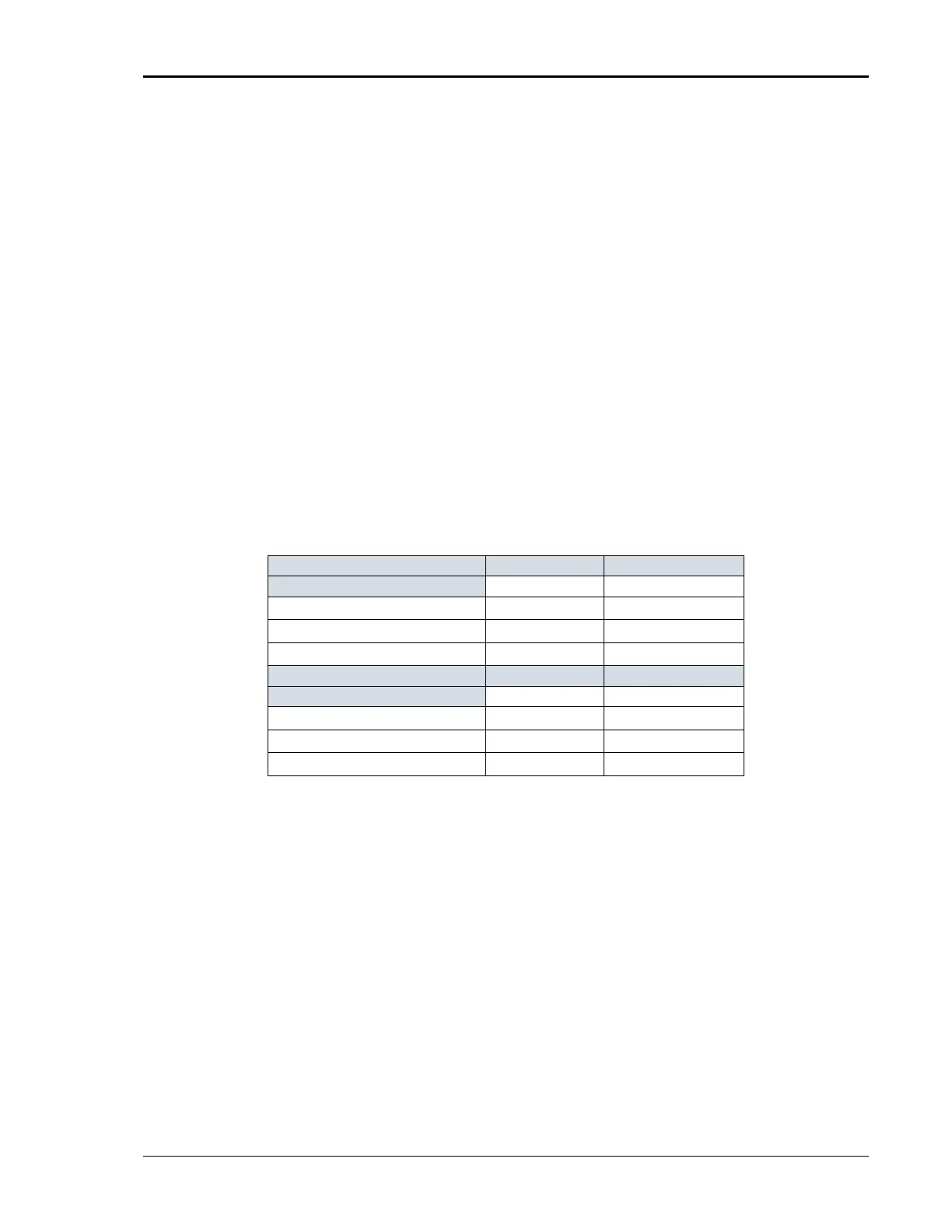
If it is necessary to adjust the pots, see Table 6-6 for the corresponding pot
designators. The top cover must be removed to access these pots. They are
located along the top edge of the controller board(s). For Series I MX units,
adjustments for phase A are on the phase A board (7000-721), adjustments for
phase B and C are on the phase B/C board (7000-722). For Series II MX units,
all adjustments are on the 7003-718 controller board. The reference designators
are the same on either series controller.
Repeat steps 2 through 11 for phase B and C. (except on single phase only
models).
Phase A (7000-721)
R121 R122
Phase B (7000-722)
R112 R111
Phase C (7000-722)
R114 R115
Phase A (7003-718-2 / -4)
R121 R122
Phase B (7003-718-2)
R112 R111
Phase C (7003-718-2)
R114 R115
Table 6-6: Programmable Z Adjustment Pots