User Manual – Rev BE AMETEK Programmable Power
MX Series 213
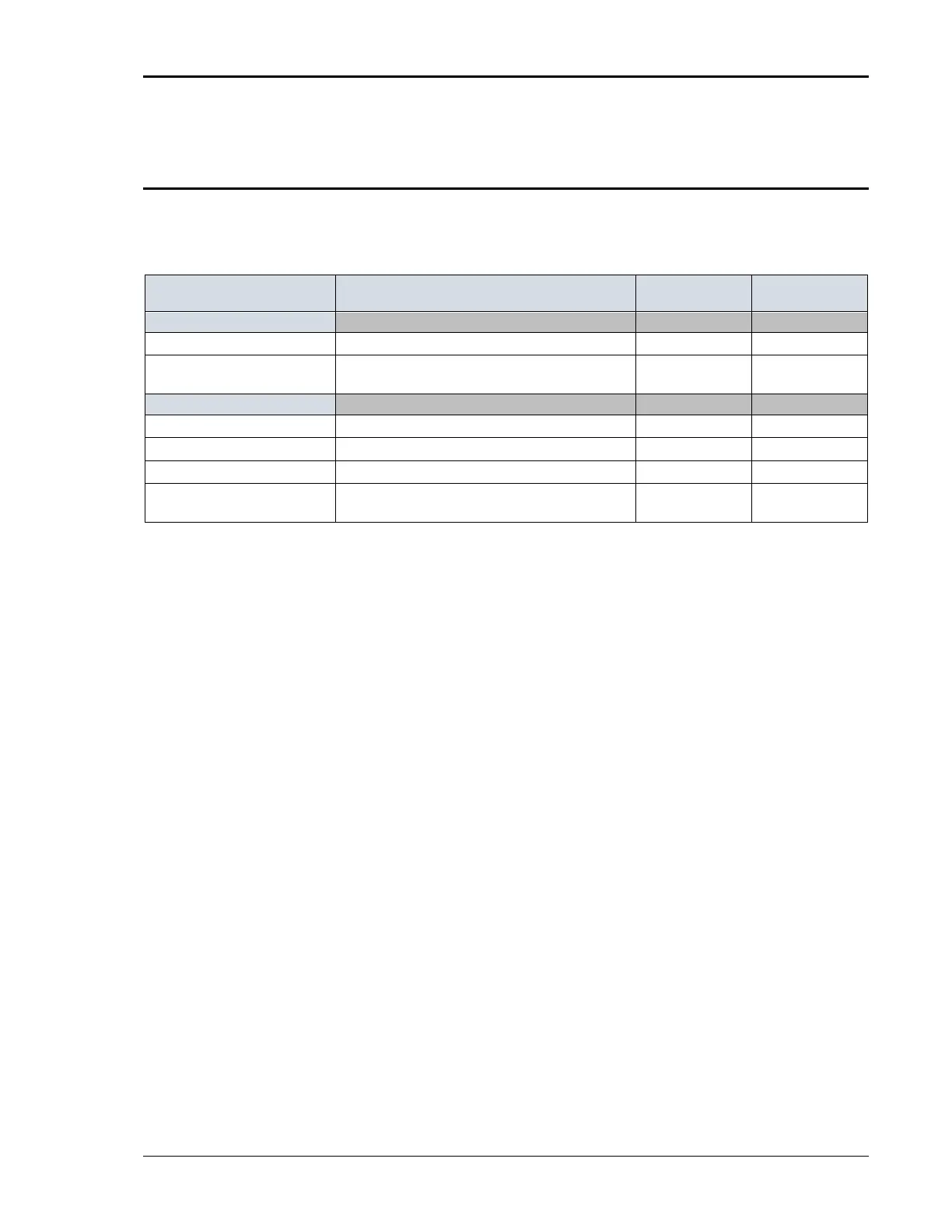
6.3.4 Measurement Calibration Summary
The following Table is a summary of the preceding calibration steps. The value
indicated by the External DVM is called V
AC
or V
DC
. The current measured by the
current shunt is called I
AC
or I
DC
.
P ROGRAM/ LOAD P ARAMETERS
AC Volt Full-scale 300 VAC Range, 240 VAC, 60 Hz, no load
VOLT FS V
AC
AC Current Full-scale
150 VAC Range, 120 VAC, 60 Hz, full load to 90% of max
current range.
CURR FS I
AC
DC Vo l t Ze r o (P/ N 7003-400 only) 400 VDC Range, +2.0 VDC, no load
VOLT ZERO V
DC
DC Volt + Full-scale 400 VDC Range, + 320 VDC, no load
VOLT FS V
DC
DC Current Zero (7003-400 only) 200 VDC Range, 160 VDC, 80 ohm load
CURR ZERO I
DC
DC Current Full-scale
200 VDC Range, 160 VDC, full load to 90% of max. current
range.
CURR FS I
DC
Table 6-2: Measurement Calibration Table
For a multi-phase power system, repeat Paragraph 6.3 for each phase. Move
the external test equipment to the phase that is being calibrated. Refer to
Figure 6-2.
While viewing the calibration screen, press the PHASE key to select the
respective phase.