User Manual – Rev BE AMETEK Programmable Power
MX Series 83
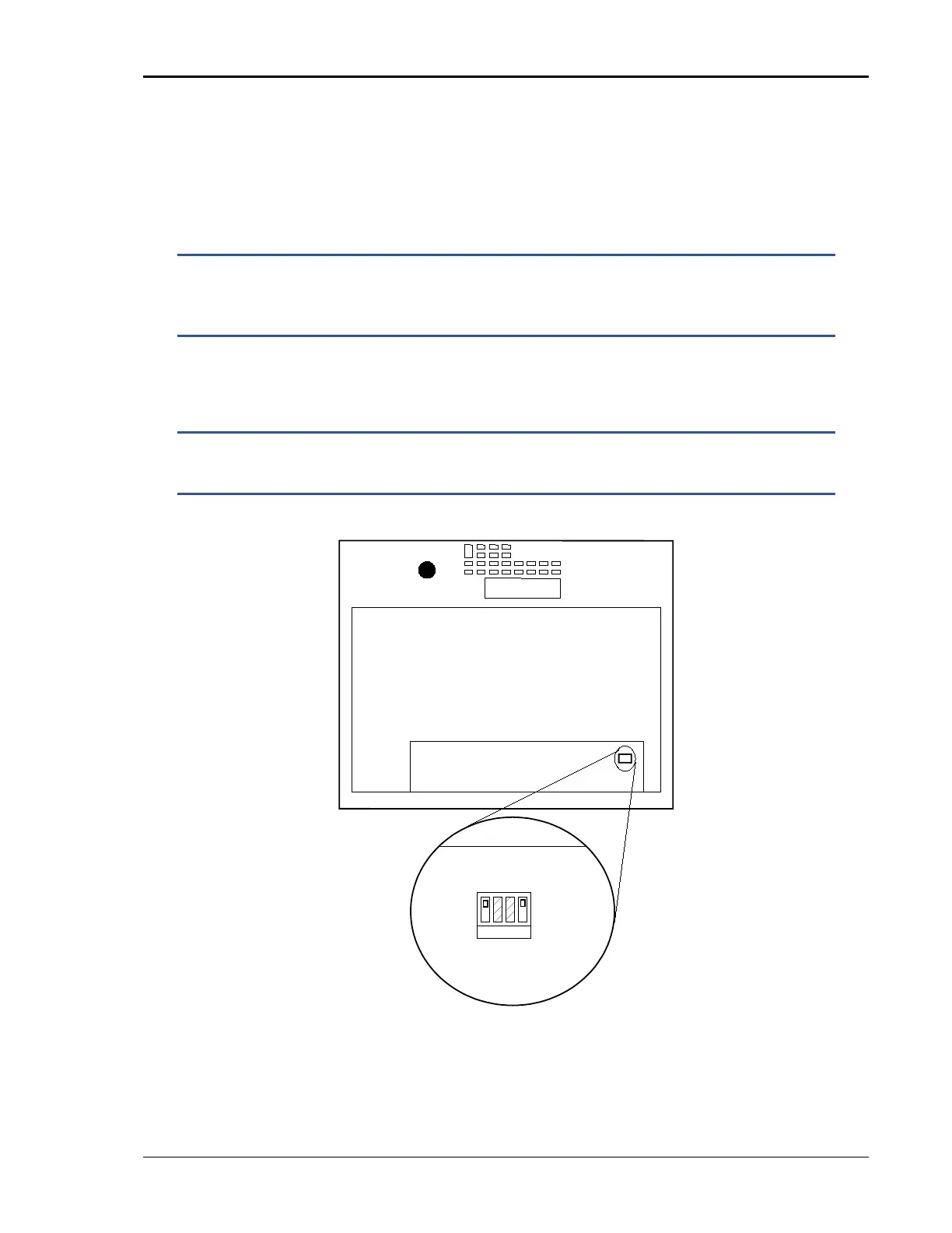
In addition to disabling the controller if present (as described above), the DIP
switch (S1) located on the GPIB / RS232C / IO assembly in the auxiliary
cabinets. (Requires removal of the top cover). The correct switch settings are
shown below. (shown set for Master cabinet). Note that all units must be
powered down before reconfiguring. Also, the output wiring must be changed to
accommodate the new configuration.
NOTE: If the units being re-configured for multi-cabinet operation
were not factory configured this way, it may be necessary to
balance the amplifiers by adjusting their gain. Refer to section
6.4 for details on Amplifier balancing.
When used as a multi-cabinet system, the system interface cables must be
connected between the master and the auxiliary cabinets.
NOTE: If the –MB system has the –ES emergency shut off switch
option, it is required to connect the ES BNC connection between
master chassis. See section
3.7.8.
Figure 3-20: Multi-Cabinet DIP Switch Location and Setting
MODE
MASTER
AUX
SINGLE-CAB
MULTI-CAB
1 2 3 4
S1
Top View
from back of MX
Interface Board
Detail
view
DIP S1
chassis