User Manual – Rev BE AMETEK Programmable Power
MX Series 34
2.6 Special Features and Options
Mo d e :
Switches between 1 and 3 phase outputs. This mode is available on models MX30-3Pi and MX45-3Pi only.
Parallel Operation:
Up to three units can be paralleled in a three-phase configuration (with one master controller and one or two auxiliary
units). (MX60, MX90 and MX135). Only the master unit requires a controller in this setup. The auxiliary units are
controlled through the system interface.
Clock and Lock Mode:
(Op t i o n -LKM and -LKS
required).
Three units (all with controllers) can be connected in a three-phase configuration using CLOCK and LOCK connections.
Each unit requires its own controller in this configuration. One unit acts as the master and provides the reference clock
to the auxiliary units.
NOTE: This option cannot be combined with –HF o pt ion .
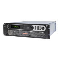
Controller:
Programmable controller front panel assembly.
Output Relay:
Standard output relay feature to isolate power source from the load.
Output On/ Off:
The output relay can be used to quickly disconnect the load. A green status indicator displays the status of the output
r ela y.
Firmware / Software Options
- 704
Mil Std 704D & E test firmware.
Mi l Std 704A, B, C, & F test software (refer to Avionics Software Manual P/ N 4994-971 for details)
NOTE: Requires use of Virtual Panels Windows application software provided on CD ROM CIC496.
- 160
RTCA/ DO-160D test firmware
RTCA/ DO-160E test software (refer to Avionics Software Manual P/N 4994-971 for details)
NOTE: Requires use of Virtual Panels Windows application software provided on CD ROM CIC496.
- 411
IEC 61000-4-11 test firmware (Pre-compliance)
- 413
IEC 61000-4-13 test firmware
-A3 5 0
Ai r b u s A350 ABD0100.1.8.1 Test software (refer to Avionics Software Manual P/N 4994-971 for details)
NOTE: Requires use of Virtual Panels Windows application software provided on CD ROM CIC496.
-ABD
Airbus A380 ABD0100.1.8 Test software (refer to Avionics Software Manual P/ N 4994-971 for details)
NOTE: Requires use of Virtual Panels Windows application software provided on CD ROM CIC496.
-AMD
Airbus AMD24C Test software (refer to Avionics Software Manual P/N 4994-971 for details)
NOTE: Requires use of Virtual Panels Windows application software provided on CD ROM CIC496.
-B787
Boeing 787 Test software (refer to Avionics Software Manual P/ N 4994-971 for details)
NOTE: Requires use of Virtual Panels Windows application software provided on CD ROM CIC496.
-WH M
Watt Hour Measurements (Accuracy and Resolution. See Sec.
2.6.3
.)
Output Voltage Range Op t i o n s
-333
Replaces the 150/ 300 AC and 200/ 400 Dc Ranges with 166/ 333 AC and 220/440 DC Ranges
- HVC
Adds 400 V AC only output range.
- HV
Adds 400 V AC only output range.
- XV
Adds customer specified AC only output range. Contact factory for details.
-ES
Emergency Shut off switch. This option key lock push button is installed on the front panel of the master MX if ordered with the
MX system. When pushed in, the main AC contactor is opened disconnecting the AC input power to the MX input transformer.
Note that the controller (and LCD display) will still be powered up, but no power is available to the amplifiers and there will be
no output power either. The controller runs off the LV supply, which must be turned off with the front panel breaker.
After the ES has been pushed, the provided key will be required to release it. Once the ES button has been released, the MX
be powered down using the front panel circuit breaker and turned back on to start up again.
NOTE: Except for MX units shipped after January 2017, multi-box MX Systems (MX60 and up) with more than one controller and
front panel controls, each having an ES switch, require that a BNC cable be connected between the cabinets for the ES
 Loading...

