User Manual – Rev BE AMETEK Programmable Power
MX Series 222
6.4.8 Option -413 Calibration
If the IEC61000-4-13 auxiliary generator option is installed, the following
calibration procedure applies. Refer to for the locations of the adjustment pots
on the Aux. Waveform Generator (CI P/N 7004-719-1).
CAUTION: This will require the top cover to be removed. Always use
caution when removing the top panel to not touch the LV
supply. This procedure should be performed by qualified
personnel only
1) Select AC mode, 300V range, 0.0 Vac, 50 Hz. Do not apply a
load. Close output relay.
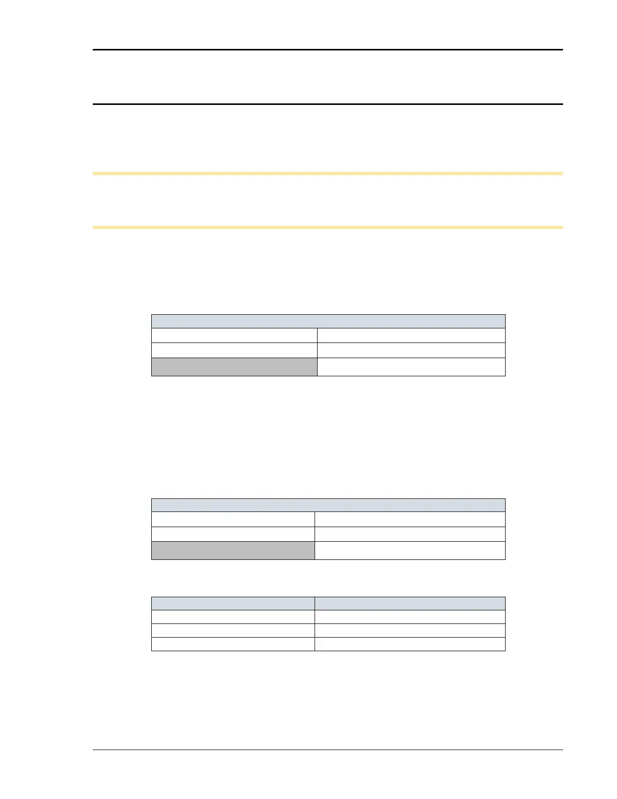
2) Select INTER HARMONICS the MENU 2 screen. The following
values will be displayed:
REF. VOLT = 0 . 0 VAC FREQUENCY = 400 Hz
VOLTAGE = 0.0% REF. COUPL = OFF
REFERENCE = OFF
3) Select REFERENCE and program ON with the shuttle.
4) Select REF VOLT and program 230.0.
5) Select VOLTAGE and program 8.7%.
6) Select FREQUENCY and program 400 Hz. This combination of
values should generate a 20.0 Vac RMS output from the AUX.
Generator. See sample below:
REF. VOLT = 230.0 VAC FREQUENCY = 400 Hz
VOLTAGE = 8.7% REF. COUP L = OFF
REFERENCE = ON
7) Adjust the respective pot for the output phase being calibrated
for a 20.0 ± 1.0 volt output on the external AC DVM.
A R9
B R1 0
C R1 1
8) For LF and FC option, Select the program screen and set alll
three phases current limit to 0.3A
9) Select FREQUENCY in the INTER HARMONIC screen and
program the frequency to 1800 Hz.