Page 1–2
UPLC-II™ System Manual
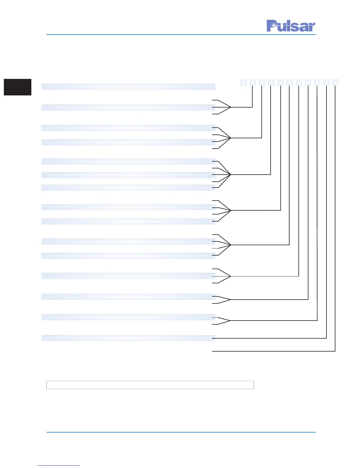
Table 1–1. UPLC-II™ Catalog Numbers
Typical Catalog Number
U S 1 N S M 7 A F S X
1 – Base Unit U
2 – Configuration
Single Transceiver Unit (3RU) w/Single Power Amplifier S
Single Transceiver Unit (3RU) w/Dual Power Amplifier
1
A
Single Receiver Unit (3RU) R
3 – Main Power Supply
48/60 Vdc 4
110/125/250 Vdc 1
48/60 Vdc w/Auxiliary Power Supply for 20/200mA Output 8
110/125/250 Vdc w/Auxiliary Power Supply for 20/200mA Output 2
4 – Redundant Power Supply
1
48/60 Vdc 4
110/125/250 Vdc 1
48/60 Vdc w/Auxiliary Power Supply for 20/200mA Output 8
110/125/250 Vdc w/Auxiliary Power Supply for 20/200mA Output 2
None N
5 – Outputs / 4–Freq. Logic
Std Outputs (7 SS, 3 Contacts) S
Std Outputs (7 SS, 3 Contacts) + 4 Trip Duty Contact Outputs E
Std Outputs (7 SS, 3 Contacts) + 4–Freq. Logic T
Std Outputs (7 SS, 3 Contacts) + 4 Trip Duty Contact Outputs + 4–Freq. Logic F
6 – Ethernet Ports
None (Front Port Present but Non-Functional) A
Front = 1 RJ-45, Rear = 2 RJ-45 (10/100 BaseT)
M
Front = 1 RJ-45, Rear = 2 Fiber ST (100 BaseFX)
P
Front = 1 RJ-45, Rear = 1 RJ-45 & 1 Fiber ST
2
R
7 – Protocols
No Protocol 7
IEC 61850 Compliant
3
8
DNP3 Compliant 9
8 – Testing Facilities (ON/OFF Checkback Test / FSK Trip Test)
Active A
None N
9 – Power Amp Features
Power Amp with Frequency Selectivity for Reflected Power F
No Power Amp – Receiver Only X
10 – Future
Reserved for Future Options S
11 – Future
Reserved for Future Options X
1
Dual Power Amps requires 2
nd
Power Supply
2
Call for availability
3
Must also select an ethernet option
1 2 3 4 5 6 7 8 9 10 11
 Loading...