January 2016 Page 7–7
Chapter 7. Communication Protocols
7
Figure 7–5.
DNP Analog Inputs / UPLC-II™ Analog Values Settings Page
(Admin > Protocol > DNP > UPLC-II™ Analog)
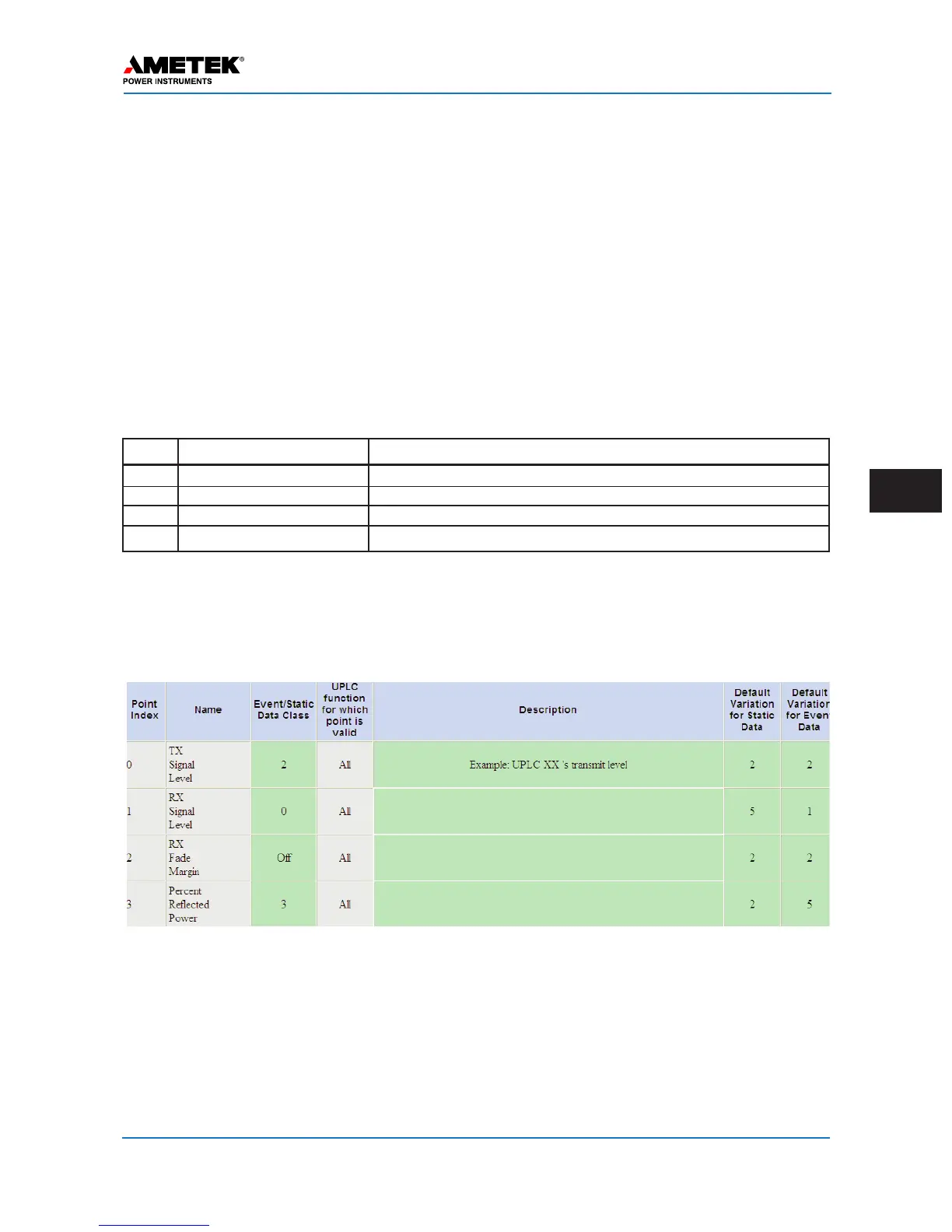
Table 7–5.
UPLC-II™ Analog Values
(All Modes)
Point Name Definition
0 TX Signal Level Measured Transmit Signal Level to Coax
1 RX Signal Level Measured Receive Signal Level from Coax
2 RX Fade Margin Measured dB RX Margin – Amount Signal can Fade & Still Work
3 Percent Reflected Power Measured % Reflected Power for TX
7.4 DNP Analog Inputs (UPLC-II™ Analog Values)
The UPLC-II™ has 4 analog UPLC™ measured values that can be set to be read via DNP.
 Loading...