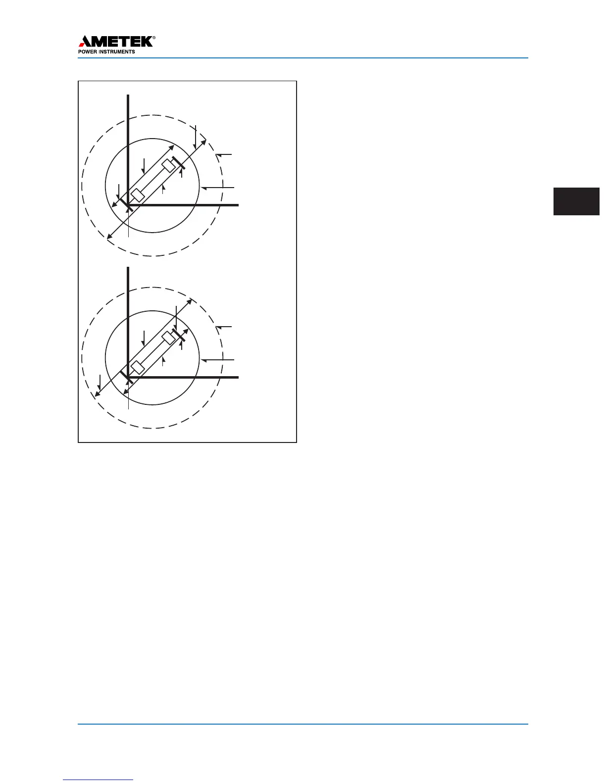
remote terminal buses; 21S must be set further than
21P, as shown.
3.2 ON/OFF Mode Special
Considerations
Because the UPLC-II™ is ON/OFF modulated,
only one frequency (f
C
) is required for line protec-
tion. When applied to three terminal lines, phase
cancellation will occur when two or more transmit-
ters are keyed simultaneously at the same frequen-
cy. To prevent this, you should offset transmitters
TX frequencies by ±100Hz. The three frequencies
should be:
•f
C
•f
C
- 100Hz
•f
C
+ 100Hz
The three receivers’ frequencies should all be set to
f
C.
If there is some scenario where both ends of a 2-
terminal line could be keyed simultaneously, the
same applies, but you only need to offset one trans-
mitter by ±100Hz. The UPLC-II™ does not have an
adjustable filter or hybrid attached to the output of
the transmitter.
If you are using the UPLC-II™ in an ON/OFF
application where no other Power-Line Carrier
equipment is attached to the power line, then no
other devices are required. However, in the appli-
cation of Single Comparator Phase Comparison
relaying, the UPLC-II™ is to be operated in the
four-wire mode, with an external skewed hybrid
between the transmitter and receiver.
If you are applying the carrier set with other trans-
mitters, coupled through the same tuning equip-
ment, you must apply a hybrid or a series LC unit to
the transmitter output to isolate the other transmit-
ters from the UPLC-II™ transmitter. This will
avoid the problems of intermodulation distortion.
We suggest that you use a hybrid if the frequency
spacing between all transmitters is within the band-
width of the hybrid (usually 6%). Check the manu-
facturers instructions for the actual spacing limita-
tions of the hybrid you are using. If you cannot use
a hybrid, then you may use a series LC unit to iso-
late the transmitters. In this case, the transmitters
must have spacing such that the LC you are using
will attenuate the external frequencies by at least
20dB (if the other frequency is a 10 watt transmit-
ter), and 30dB (if the other frequency is a 100 watt
transmitter).
3.3 ON/OFF Mode Typical
Wiring/Connections
Common wiring/connection diagrams for ON/OFF
applications can be found on the following pages.
January 2016 Page 3–7
Chapter 3. Applications
3
1
2
X
Bus H
Bus G
21 S at Breaker
21 P at Breaker
R
Z
C
Z
C
Z
A
Z
A
1
2
X
Bus H
Bus G
21 S at Breaker
21 P at Breaker
R
Z
C
Z
C
Z
A
Z
A
Figure 3–4. Single Phase-Comparison
Blocking, Distance-Supervised Operation

 Loading...