Page 3–28
UPLC-II™ System Manual
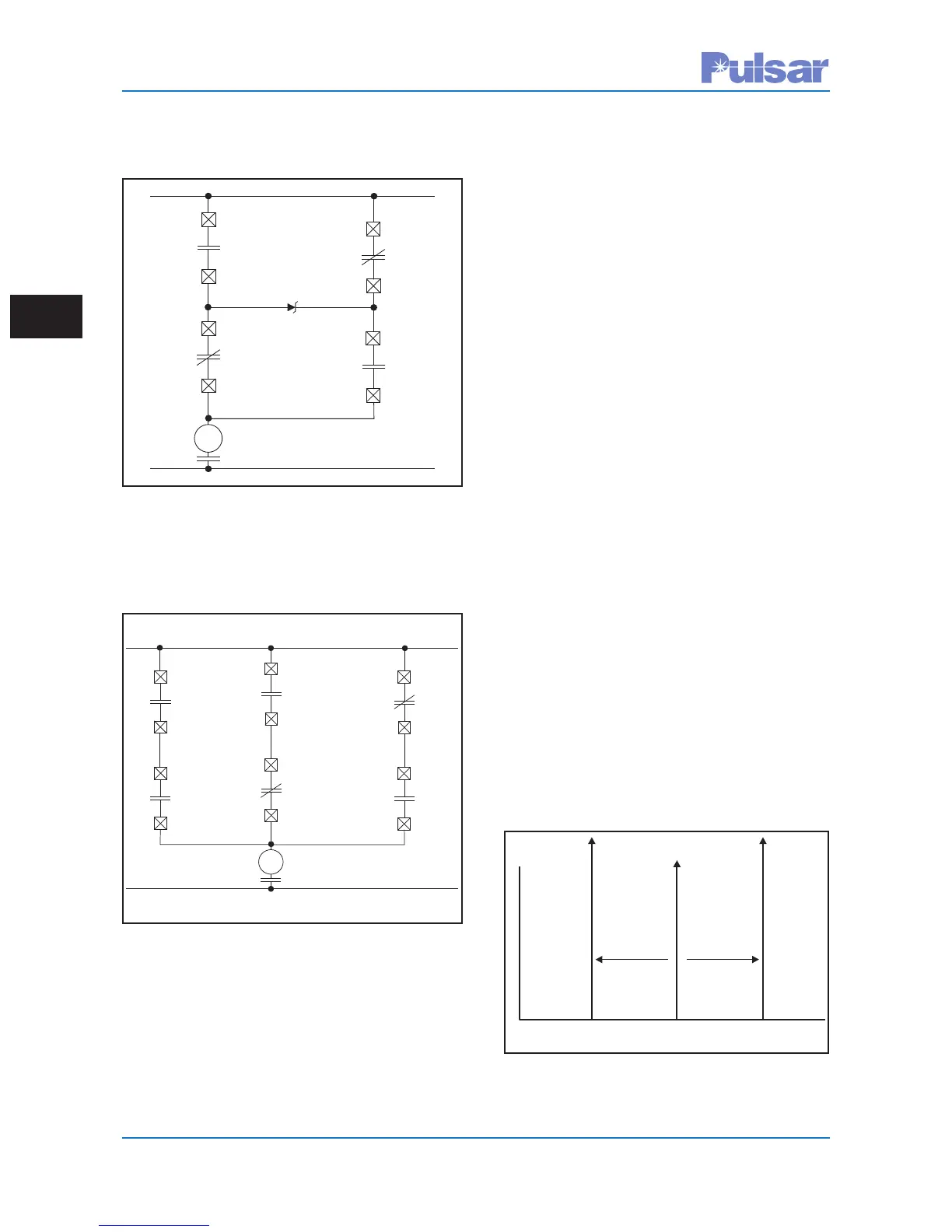
3.7 FSK Mode Special
Considerations
The UPLC-II™ frequency-shift equipment can
operate in either the two- or three-frequency mode.
The three basic frequencies are as follows (see
Figure 3–21):
f
C
Center frequency
f
H
High-frequency, is a frequency shift (Δf)
above f
C
f
L
Low-frequency, is a frequency shift (Δf)
below f
C
The value of Δf depends on the bandwidth of the
UPLC-II™ set. For a bandwidth of 1200 Hz, Δf is
500 Hz. A bandwidth of 300 Hz yields a Δf of
100 Hz, while the 600 Hz bandwidth Δf can be
either 250 or 100 Hz. The center channel frequency
(f
C
) can vary from 30 to 535 kHz (in .01 kHz
steps).
In the two-frequency systems, only f
H
and f
L
are
used. The two frequencies function differently and
take on different labels when operating with the dif-
ferent types of protective relay systems.
TB6–1
TB6–2
Channel1DTT
TB4–1
TB4–6
TB6–2
TB6–1
TB4–6
LossofChannel1
L
ossofChannel2
Channel2DTT
*Outputisnormallyenergized,
thereforecontactwouldbeopen
T
B4–1
LOR
(–)
(+)
*
*
Figure 3–19.
Dual Channel Direct Transfer Trip with
Throwover
to Single Channel
TB6–1
TB6–2
Channel1DTT
Channel1DTT
TB4–1
TB6–3
TB4–6
TB6–4
TB6–2
TB6–4
TB6–1
TB6–3
TB4–6
LossofChannel1
LossofChannel2
Channel2DTT
*Outputisnormallyenergized,
thereforecontactwouldbeopen
*
*
Channel2DTT
TB4–1
LOR
(–)
(+)
Figure 3–20.
Dual Channel Direct Transfer Trip with
Throwover
to Single Channel
f(f– f)
LC
D f(f+f)
HC
Df
C
Amplitude
DTTTrip
(Trip1)
UnblockTrip
(Trip2)
(Guard)
Figure 3–21. UPLC-II™ 3-Frequency System
 Loading...