Page 3–40
UPLC-II™ System Manual
3.10.1 Examples
Following are several figures that illustrate possible
hybrid applications. A short description of each fol-
lows.
In these illustrations, Balanced (resistive Hybrids)
are denoted as R Hybrids, Reactive Hybrids as X
Hybrids and Skewed Hybrids as S Hybrids. Fig. 3–
29 illustrates two transmitters being combined onto
a single coax cable for connection to a line tuner.
This would be a typical application for a dual chan-
nel, uni-directional trip system. The receive end of
the system would not require a hybrid so that the
receivers would be tied together via a T-connector
and coax cable before connection into the line
tuner. However, a single 50 Ω non-inductive resis-
tive load should be bridged across the high imped-
ance receivers to terminate the line tuner because
there is no 50 Ω ouput transmitter also present.
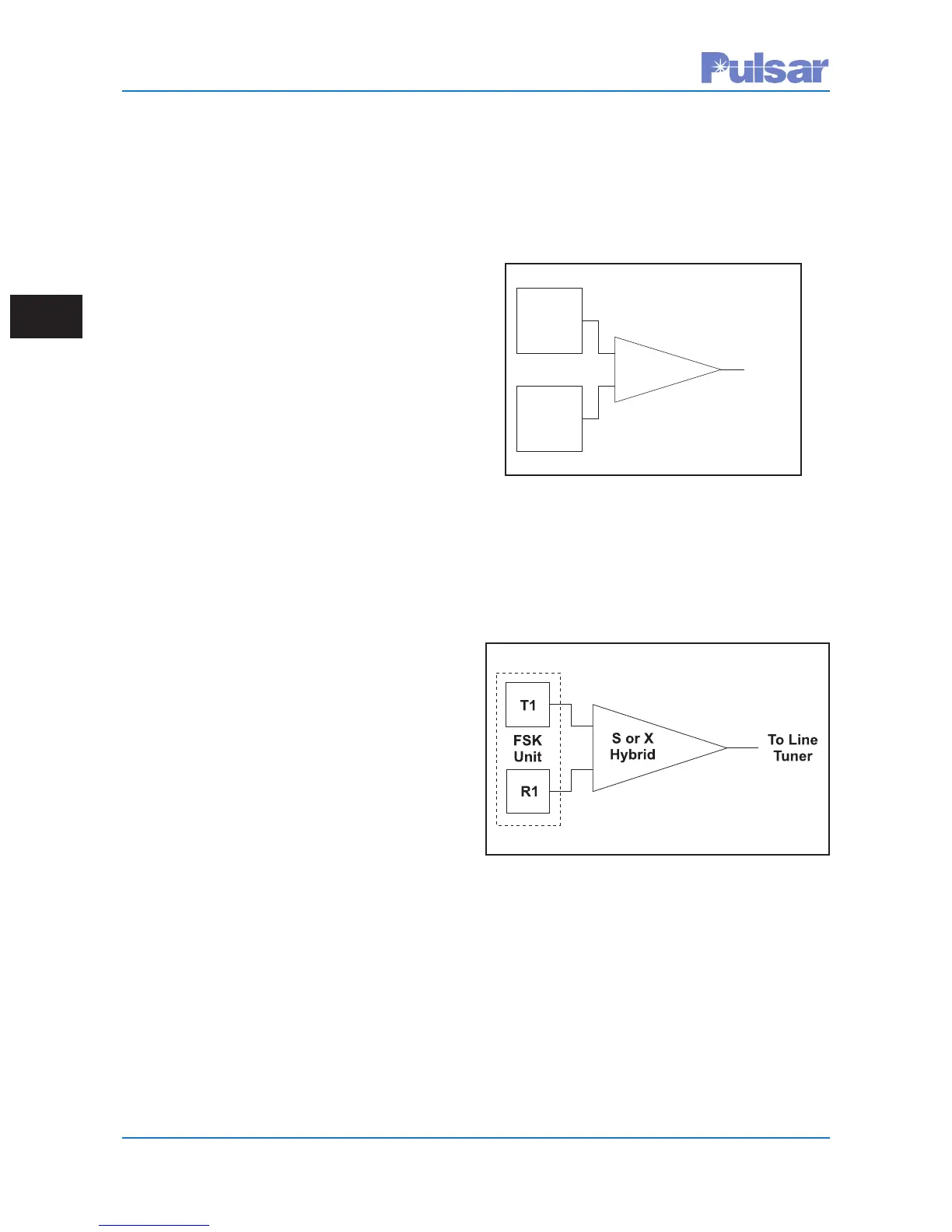
When only one transmitter and one receiver are
required as in a single channel bi-directional trans-
fer trip system or a directional comparison unblock-
ing system Fig. 3–30 can be applied. A skewed
hybrid may be used in place of the reactive hybrid
(X hybrid). The skewed hybrid has a designated
transmit port and receive port.
When two transmitters and two receivers are being
applied to a single coax cable, as in a dual channel
bi-directional direct transfer trip system, Fig. 3–31
is appropriate.
When combining a DCB blocking carrier with a
dual channel bi-directional DTT, Fig 3–32 is appro-
priate. The setup gives less hybrid loss for the
ON/OFF DCB vs the FSK DTT, because the
ON/OFF DCB requires a better signal/noise ratio.
T
1
T2
XHybrid
T
oLine
T
uner
Figure 3–29. Hybrid Connections – Two
Transmitters
Figure 3–30. Hybrid Connections – Single Bi-
Directional Channel
 Loading...