Copyright © AMETEK Page 4–1
4. Test Equipment
4
!
CAUTION
We recommend that the user of this equipment become thoroughly acquainted with the information in
these instructions before energizing the UPLC-II™ and associated assemblies. You should not remove or
insert printed circuit modules while the UPLC-II™ is energized
2
. All integrated circuits used on the mod-
ules are sensitive to and can be damaged by the discharge of static electricity. You should always observe
electrostatic discharge precautions when handling modules or individual components. Failure to observe
these precautions can result in component damage.
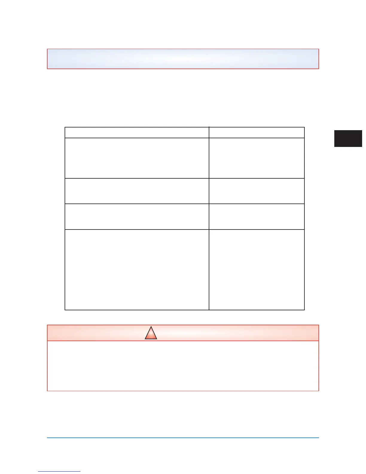
Table 4–1. Recommended Test Equipment
Equipment Application
High-Impedance Frequency Selective Level Meter Checking TX/RX Levels
1 kHz to 1 MHz Checking Noise Levels
• PowerComm Solutions PCA-4125
• Signal Crafters Model 110
• Spectrum Analyzer
Reflected Power Meter Adjusting Line Tuner to Match
• Signal Crafters Model 70 UPLC-II™ Output Impedance
• PowerComm Solutions PCA-4125
Signal Generator For Setting RX Sensitivity when
• Signal Crafters Model 90 or 110 no Remote TX is Available
• PowerComm Solutions PCA-4125
Non-Inductive Resistor, 50 or 75Ω, 25Ω Transmitter Termination
• Opek DL-60: 50Ω, 20W Load
1
(For Calibration)
• DX Engineering DL30A: 50Ω, 15W Load
1
Loads Also Included in the Following Equipment
• PowerComm Solutions PCA-4125:
50Ω, 18W Input
• PowerComm Solutions Model 630:
50Ω, 25W Load
• Signal Crafters Model 70:
50Ω, 50W Load
Recommended Test Equipment
Table 4–1 shows the equipment used to test, service and verify your UPLC-II™ unit.
1
Requires a UHFFemale to BNC Female Adapter to Interface Directly to the UPLC-II™.
2
Except for Power Amp and Power Supply Modules.
 Loading...