January 2016 Page 3–37
Chapter 3. Applications
3
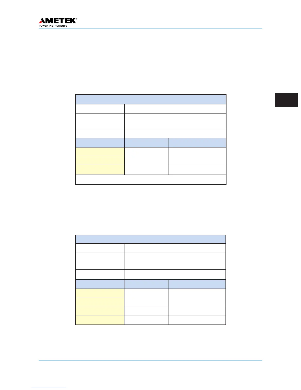
Table 3–7.
Software Programmable Alarms/(Outputs from I/O Board)
FSK Mode
Hardware Failure Alarm for All UPLC-II™ Units
Alarm Reason: Hardware health of at least one card is bad
Alarm Name: General Alarm Output
(Available Outputs) (LL08 – LL10)
De-Energized State
Contact Type: N.O. Contact N.C. Contact
UPLC-II™ Condition
All OK Closed Open
Hardware Failure Open Closed
Loss of DC Power Open Closed
Table 3–6.
Hardware Fixed Alarm (from Power Supply Board)
All Modes
Hardware Failure Alarm for All UPLC-II™ Units
Alarm Reason: One of the PS outputs is too low in voltage
Alarm Name: Power Supply Alarm Output
(Available Outputs) (TB1-5 & 6)**
De-Energized State
Contact Type: N.O. Contact N.C. Contact
UPLC-II™ Condition
PS Good Closed Open
PS Bad Open Closed
**For the Redundant Power Supply, use TB2-5 & 6
3.9 FSK Mode Alarms
The following tables show alarms for FSK mode.
 Loading...