Page 3–38
UPLC-II™ System Manual
* Fade alarm is not fail-safe and has a different state for the alarm condition vs loss of DC power. Also Good Channel output
must be used on outputs LL08-LL10 in order to be fail-safe as shown in this table.
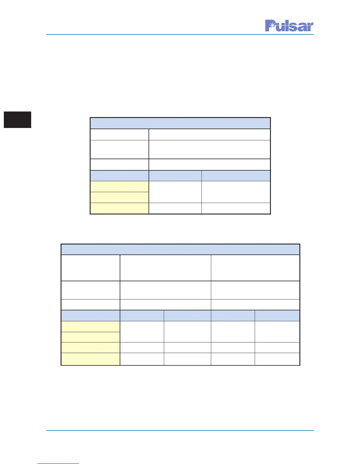
Transmit Alarm for FSK Units Only
Alarm Reason: TX signal level is ≥ TX low level setting
Alarm Name: Main RF Output (LL01 – LL10)
(Available Outputs)
De-Energized State
Output Type: N.O. Output N.C. Output
UPLC-II™ Condition
Transmit ON Closed Open
Transmit OFF Open Closed
Receive Alarms for FSK Units Only
Alarm Reason: Early Warning alarm, RX signal Receiver stopped working, RX
level has dropped below settable signal has dropped below Fade
Fade Alarm threshold Margin or RX Freq. too far off
Alarm Name: Fade Alarm Output Good Channel Output
(Available Outputs) (LL01 – LL10) (LL01 – LL10)
De-Energized State De-Energized State
Output Type: N.O. Output N.C. Output N.O. Output N.C. Output
UPLC-II™ Condition
RX Signal Normal Open Closed Closed Open
RX Signal Low Closed Open Open Closed
Loss of DC Power Open Closed Open Closed
Table 3–7 Continued:
Software Programmable Alarms/(Outputs from I/O Board)
FSK Mode
 Loading...