January 2016 Page 2–5
Chapter 2. Product Description
2
2.2 Standard Nomenclature
The standard nomenclature for AMETEK carrier protection equipment is as follows:
Cabinet – contains fixed-racks, swing-racks, or open racks
Rack – contains one or more chassis (e.g., the UPLC-II™)
Chassis – contains several printed circuit boards, called modules (e.g., Power Supply or Transceiver)
Module/Card/Board – contains a number of functional circuits (e.g., Oscillator or Microprocessor)
Circuit – a complete function on a printed circuit board
2.3 UPLC-II™ Chassis
The Front Panel requires a screwdriver to open. It is shown in Figure 2–1. See Figure 2–2 for the back-
plane. The UPLC-II™ chassis specifications (see Figure 2–3) include standard dimensions of:
Height – 5.25” (133.35 mm), requiring 3 rack units, each measuring 1.75” (44.45 mm)
Width – 19.00” (482.6 mm) Depth – 13.50” (342.9 mm)
The chassis includes a two-piece metal cover plate on back. The top half of the cover plate is easily remov-
able with 4 captivated screws fastening it. Loosen screws, pull bottom out then down to remove.
Each chassis is notched for mounting in a standard 19” rack and has adjustable mounting brackets on the
sides. It may be flush-mounted against another chassis on top & bottom.
2.4 UPLC-II™ Modules
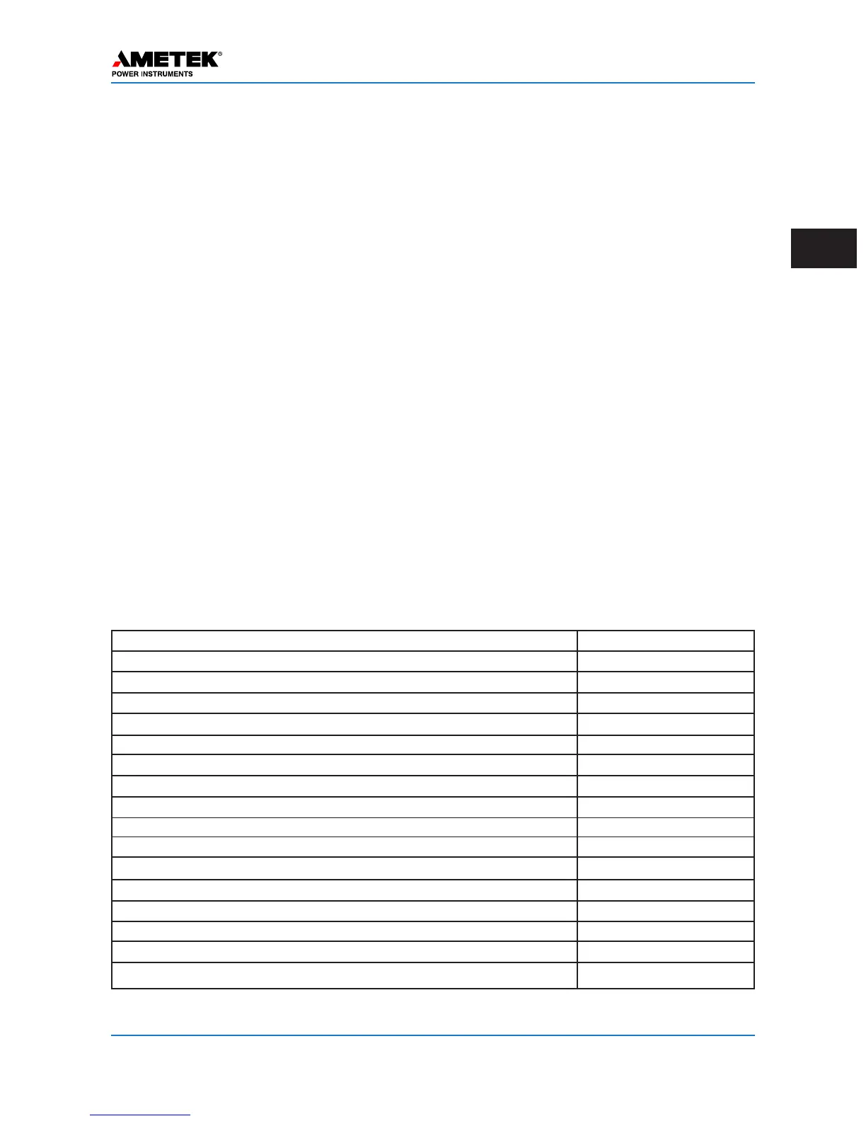
The basic UPLC-II™ has 7 standard printed circuits boards in a 3RU 19 inch chassis. There are 4 addi-
tional boards that may be supplied, based upon the catalog number purchased. These modules are:
The block diagram, illustrating how these are all interconnected is on Page 2–22.
Name Part Number
Power Supply (Main / Optional Redundant) 110/125/250 Vdc CU20-PS1MN-001
Power Supply (Main / Optional Redundant) 48/60 Vdc CU20-PS1MN-002
Power Supply (Main / Optional Redundant) 110/125/250 Vdc w/Aux. PS CU20-PS1MN-101
Power Supply (Main / Optional Redundant) 48/60 Vdc w/Aux. PS CU20-PS1MN-102
Power Amplifier (Main / Optional Redundant) CU20-PA1MN-002
Display Board CU20-DP1MN-001
Aux. Display board – w/Ethernet RJ-45 & RS-232 DB9 connectors CU20-DP1A3-001
Input/Output Board CU20-IO1MN-001
Transceiver Board CU20-XVRMN-001
Ethernet Board (Optional) – 2 RJ-45 (10/100 BaseT) CU20-XVRA5-001
Ethernet Board (Optional) – 2 Fiber ST (100 BaseFX) CU20-XVRA6-001
Ethernet Board (Optional) – 1 RJ-45 & 1 Fiber ST CU20-XVRA7-001
Aux. PS (Optional) – for powering 20V, 20 or 200 mA outputs CU20-PS1A1-001
Motherboard/Backplane CU20-BP1MN-101
Front Door (without auxiliary door board) 1088-524
Chassis (complete with backplane & front door) 1087-177
Table 2–11. UPLC-II™ Modules and Part Numbers
 Loading...