Page 2–4
UPLC-II™ System Manual
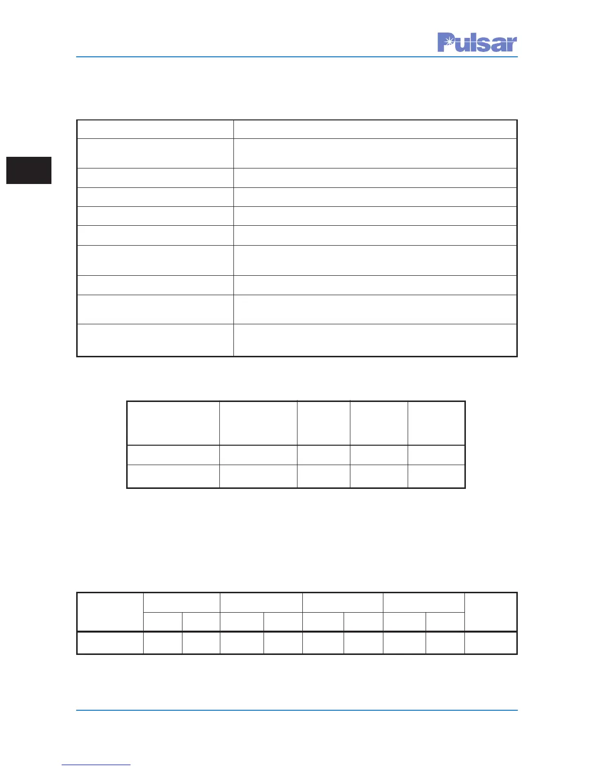
Table 2–9. Input Power Requirements
Nominal Battery Permissible Standby 1 Watt 10 Watt
Voltage Voltage Range * Transmit Transmit
Range Single Single
48/60 Vdc 38 to 76 Vdc 25 watts 35 watts 60 watts
110/125/250 Vdc 88 to 300 Vdc 20 watts 30 watts 66 watts
*Not transmitting
Permissable ripple on incoming Vdc = 5%
Maximum allowable frequency of ripple = 120 Hz
Unit can also operate with 110–130 Vac input
* Without redundant Power Supply or Power Amp.
Table 2–10. Weight & Dimension Specifications
Equipment Net Weight* Height Width Depth Rack
lbs Kg inches mm inches mm inches mm Space
Single Unit 21 9.53 5.218 132.54 17.437 444.88 13.26 336.75 3 RU
Table 2–8. Environmental/Surge/Interface Specifications
Ambient Temperature, range of air –30 C to +70 C (ANSI C37.90)
Relative Humidity Up to 95% (non-condensing) at 40 C (for 96 hrs cumulative)
(ANSI C93.5)
Altitude Up to 1500 m (without de-rating), 6000 m with de-rating
Surge Withstand Capability Per ANSI C37.90.1
1 Minute withstand IEC 255-5 and C37.90 (500 Vdc class)
Coax, center conductor to ground 3000 V impulse level, 1.2 x 50 µs impulse, per ANSI C93.5
Dielectric Per ANSI C37.90, 500 Vdc class (3,000 Vdc dielectric
withstand), IEC 60255-5
Electrostatic Discharge (ESD) Per ANSI C37.90.3, IEC 61000-4-2
Radiated Electromagnetic Per ANSI C37.90.2
Interference from Tranceivers
Carrier Frequency on dc Input 20 mV (max.)
Leads When Transmitting 1 W
 Loading...