January 2016 Page 5–17
Chapter 5. Installation/Commissioning Procedure
5
particular tab. The tab that is seen first is the
G
eneral Settings for the connected unit. The bold
items are the set items which can be changed. The
settings shown in blue are actual hardware jumper
settings, which are sensed and can not be changed
in the software.
If the user account you have used to log into the
UPLC-II™ is set to “User” rights then you will see
a “Change Settings” button below the Current
Settings table on the web page. If you do not see
this button then your user account does not have
rights to make changes to the settings and you can
only view the settings. You must then logon with a
user name that has rights to make changes if you
desire to change the settings.
5.7.1 General Tab
When you click on the change settings button on the
General settings page (Fig. 5–6 & 5–7), you will see
the first items that need to be selected. At the top, is
the System ID1 and System ID2 Setting. These two
boxes allow you put an identification you want the
unit to show in the Title bar of the web pages. One
suggestion here might be to identify the substation
name with the line name and breaker number that
the carrier set’s associated relaying is connected to.
The last item to select is the most important. That is,
do you want this unit to be a Frequency Shift Keyed
(FSK) or ON/OFF type? This setting will affect all
the other settings you are presented on the next
pages.
On the second screen of the General Settings Tab
you will see more items to set. These items depend
on whether ON/OFF or FSK is selected. See Table
5–4 and Table 5–5 for the setting options that
a
ppear.
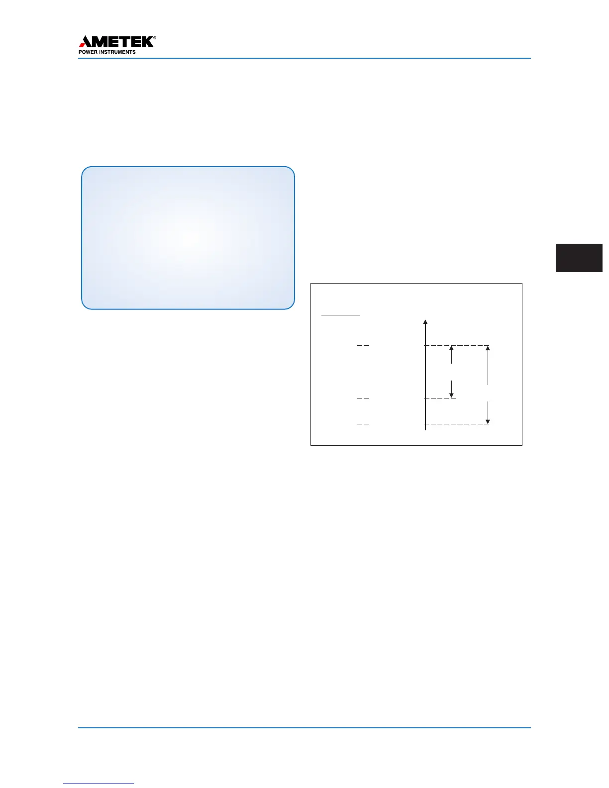
The RX sensitivity setting is not input directly but
is a level automatically calculated when the receiv-
er is calibrated. It is the minimum level at which the
receiver will work. It is equal to the fade margin dB
amount below the RX level at which the last cali-
bration was done. The RX fade alarm setting gives
an early warning alarm output when the RX signal
drops by the dB level to which it was set. But the
RX fade margin is the dB drop level at which the
receiver stops working. Therefore the RX fade
alarm is always set for a lower dB amount than the
RX fade margin. See the following
figure.
RX Fade Alarm & Fade Margin
If the unit is a Transceiver, it can also be set to TX
only or RX only if desired. Changing this setting
does erase all the I/O selections requiring them to
be selected.
This concludes the General settings on the unit.
When complete, click on the “Continue” button and
you will be taken to the Logic Tab.
NOTE:
Once any settings on a web page are made you must
always click on the “Continue” button, if not, you will
lose these settings changes. You will then automati-
cally be directed to the next successive screen for the
settings. And if you had made any changes on the
last page you will see a narrow red bar appear at the
top of the window that has the words “Changes
Pending” in it. This indicates that settings changes
have been made and have not been sent to the
UPLC-II™ yet. If you shut down your computer at this
point you will lose these settings.
Example
Levels
RXSignal
Level,dB
+20dBm
RXFade Alarm
(default=10dB)
RXFadeMargin
(default=15dB)
+10dBm
+5dBm
NormalRX
SignalLevel
(RXCal.Level)
Fade Alarm
Output
RXSensitivity
*
*
(RXstopsworking,lossofgoodchanneloutput)
 Loading...