Page 5–20
UPLC-II™ System Manual
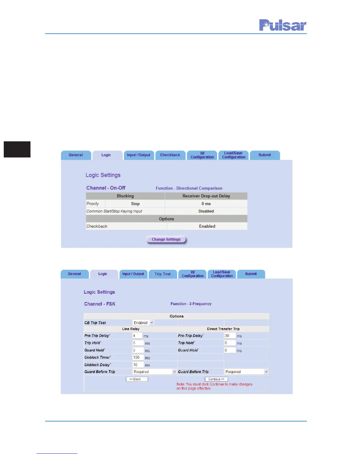
Figure 5–8. Example of The Logic Tab on the Settings Page (ON/OFF Mode)
Figure 5–9. Example of The Logic Tab on the Settings Page (FSK Mode)
5.7.2 Logic Tab
See Fig. 5–8 (ON/OFF Mode) & 5–9 (FSK Mode). In the logic settings all the time selections are changed
in increments of 1 ms. The others are similar. See Chapter 2 for definitions of the various logic settings.
ON/OFF Directional Comparison & Phase Comparison Logic settings are shown in Table 5–6.
Caution should be taken when considering setting receiver dropout delay to anything other than 0
ms. Applying a setting of 1 – 15 ms can adversely affect relaying logic such as transient blocking
logic.
FSK Logic settings for the different functions are shown in Tables 5–7 through 5–11.
Note that GBT=Guard Before Trip.
When you have completed the logic settings click the “Continue” button.
 Loading...