January 2016 Page 5–21
Chapter 5. Installation/Commissioning Procedure
5
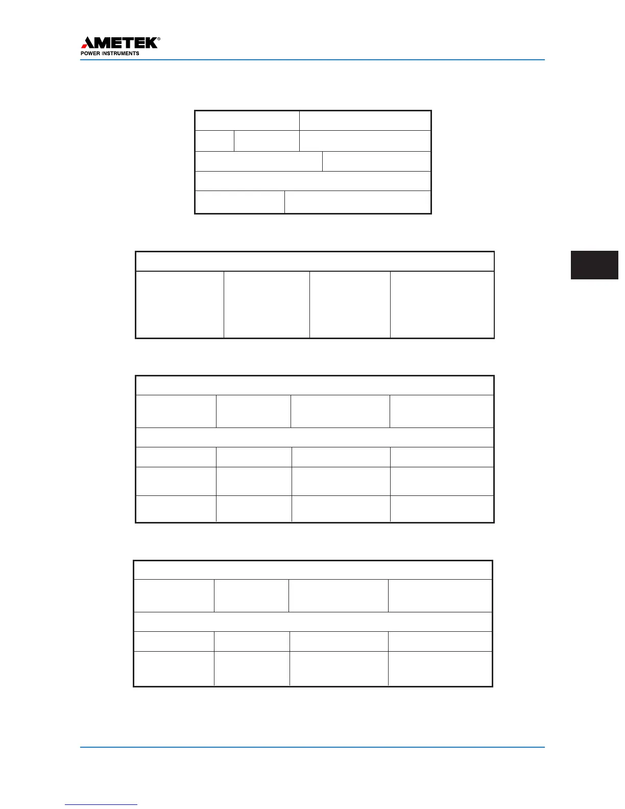
Receiver Logic
Channel Trouble TP & TN Polarity HF = TP
Clamps to “1” & LF = TN
TP & TN LF = TP
Clamps to “0” & HF = TN
Table 5–7. Logic Settings for Phase Comparison (FSK Mode)
Options
Trip Test Enabled
or Disabled
Receiver Logic
Pre-Trip Delay* 0 to 30 ms Guard Hold 0 to 100 ms
Trip Hold 0 to 100 ms Guard Before Trip None, GBT or GBT
with Override
Unblock Timer 0 to 500 ms Unblock Delay 0 to 100 ms
Table 5–8. Logic Settings for 2F Unblock (FSK Mode)
Options
Trip Test Enabled
or Disabled
Receiver Logic
Pre-Trip Delay* 0 to 30 ms Guard Hold 0 to 100 ms
Trip Hold 0 to 100 ms Guard Before Trip None, GBT or GBT
with Override
Table 5–9. Logic Settings for 2F POTT/DTT (FSK Mode)
Blocking Receiver Drop-out Delay
Priority Start or Stop 0 to 15 ms
Common Start/Stop (KA-4) Enabled or Disabled
Options
Checkback Enabled or Disabled
Table 5–6. Logic Settings for ON/OFF
(Directional Comparison & Phase Comparison)
* For every msec of pre-trip delay you add, the security, against noise causing a false trip, increases exponentially.
UB&POTT: A min of 2-4 msec is recommended.
DTT:The time delay should be as long as the critical stability of your system can tolerate, at least 10 msec min.
 Loading...