Page 2–20
UPLC-II™ System Manual
Description Part Number Digit 6 of
UPLC-II Cat. No.
Ethernet Module dual RJ-45 electrical CU20-XVRA5-001 M
Ethernet Module dual ST Fiber CU20-XVRA6-001 P
Ethernet Module dual 1 RJ-45 elec, 1 ST Fiber CU20-XVRA7-001 R
2.4.6 Ethernet Module
Description
The Ethernet module is an optional daughter board
that plugs onto the Transceiver board and is
attached by 3 screws. If this option is not pur-
chased, then none of the Ethernet ports will be
available on the UPLC-II™, although the front
port will physically be present, it will not work.
The Ethernet board supports 3 Ethernet ports, two
on the rear which are part of this board, and one
on the front panel. The front port is completely
isolated from the 2 rear ports and is intended sole-
ly for PC interface. The rear Ethernet ports can be
used for PC interface, connection to an Ethernet
network, or for other features such as DNP3 or
IEC61850 communication.
There are 2 modes of operation for the 2 rear
ports. This mode of operation is selected on the
ADMIN web page of the UPLC-II™. They can
operate:
• One as a standby/redundant port for the
other. (Default Mode)
• Like Ethernet switch ports allowing daisy
chaining of other UPLC™/UPLC-II™s or
Ethernet connected devices with itself.
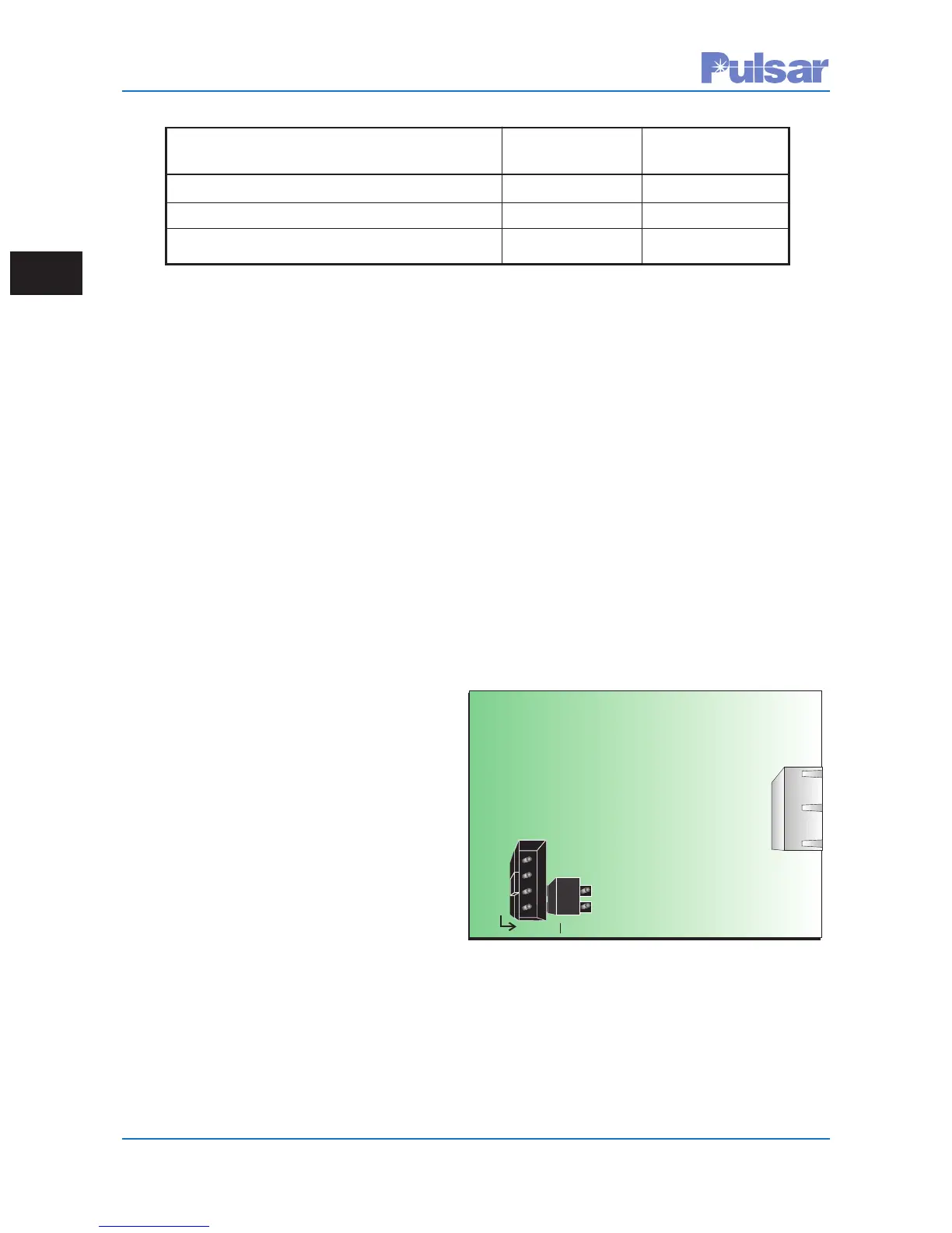
Customer interface points:
• Connector (J5) – Only used when placing
this board on older style Transceiver
boards in UPLCs to add front port
Ethernet when doing hardware upgrades.
Requires a ribbon cable assembly, part #
1088-256, to be plugged into connector J5
of this Ethernet board with the other end
plugged into connector J1 on the back of
the front display board. The UPLC-II™ does
not need this cable.
• Jumper (JMP1/2) – Always set to the ON
position for UPLC-II™s but, if putting this
board into a UPLC™ with an older
Transceiver PC board CU50-XVRMN rev 8
or lower, this jumper has to be set to the OFF
position. It works in conjunction with con-
nector J5 above when adding a front
Ethernet port to an existing older UPLC™
allowing the older Transceiver board to still
be used.
• Ethernet connectors (J3 – RJ45 or U2/U4-
Fiber ST) - Located on rear of board and
sticks out through a rectangular cutout in the
back of chassis backplane.
P
L
A
C
E J
U
M
P
E
R P
E
R
C
U
5
0
-
X
V
R
M
N R
E
V #
≥≤9 ON OFF 8
J5
JMP1
JMP2
Not to Scale for Reference Only
Component Side
J3
Figure 2–11. Ethernet Module
Connectors/Jumpers
 Loading...