Page 7–4
UPLC-II™ System Manual
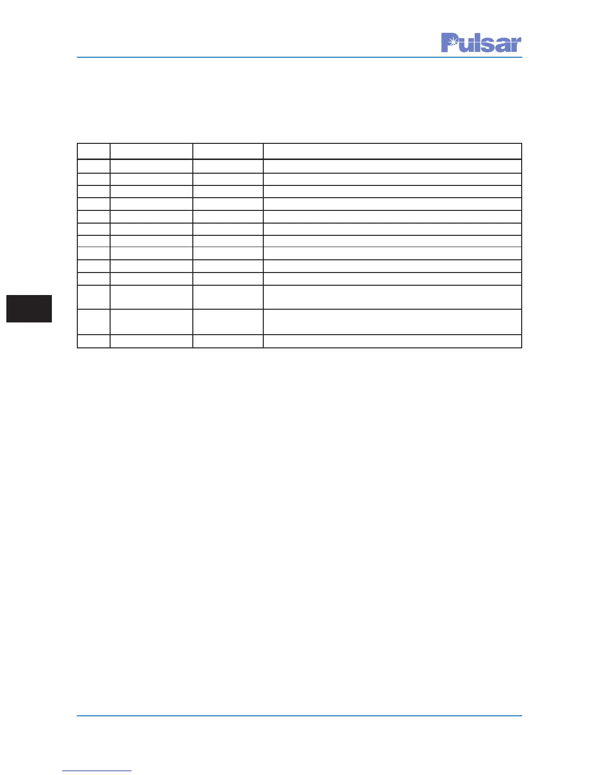
Table 7–2.
UPLC-II™ Inputs – DNP Points
(FSK Mode)
Point Name Setting Mode Definition
0 3F DTT Trip Key 3-Freq. Only DTT Trip Input Keyed (for 3–Freq. Mode)
1 LR Trip Key 2 or 3-Freq. Line Relaying Trip Input Keyed (Unblock/2F, UB/POTT/3F)
2 TX Power Off Key All FSK Modes TX RF Power Off Input Keyed (Turns TX Off for Test)
3 TX Pwr Boost Key All FSK Modes Power Boost Input has been Keyed
4 User SOE 1 Key All FSK Modes SOE Event 1 Input has been Keyed
5 User SOE 2 Key All FSK Modes SOE Event 2 Input has been Keyed
6 User SOE 3 Key All FSK Modes SOE Event 3 Input has been Keyed
7 PC Key Phase Comp. Phase Comparison Input has been Keyed
8 Trip A Key 4-Freq. Only Trip Channel A Input has been Keyed
9 Trip B Key 4-Freq. Only Trip Channel B Input has been Keyed
10 Initiate Trip Test Testing Only Trip Test Input has been Keyed
Option Enabled (for Testing Purposes Only)
11 2F DTT/POTT 2-Freq. Only DTT Trip of POTT Trip Input has been Keyed
Trip Key
12 TX Keyed Off All FSK Modes Transmit Keyed Off
7.3 DNP Binary Inputs
(UPLC-II™ Outputs)
The UPLC-II™ has 10 or 14 binary outputs,
depending on the model. Like UPLC-II™ inputs,
you can assign these outputs in numerous ways.
The following tables include all possible output
selections for the UPLC-II™ ON/OFF and FSK
modes. Since there are more selections than out-
puts, at any given time some of these selections will
be unassigned and their on-line bits will be set to
zero.
 Loading...